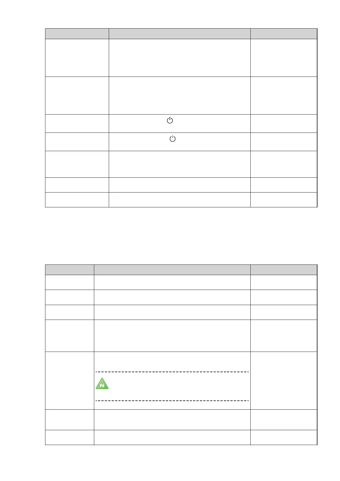
Menu selection Meaning Factory setting
START FLOW CIRC. Speed control of the heating system’s circulation pump in Volts.
Higher voltage gives a greater circulation pump speed, which
gives a lower temperature difference. A low voltage gives a
greater difference.
3 - 10 = Manually adjustable speed, where 3 is low voltage and
10 is high voltage.
7V
(range: 3V / 10V)
START FLOW BRINE Speed control of the brine system’s circulation pump in Volts.
Higher voltage gives a greater brine pump speed, which gives a
lower temperature difference. A low voltage gives a greater dif-
ference.
3 - 10 = Manually adjustable speed, where 3 is low voltage and
10 is high voltage.
10V
(range: 3V / 10V)
CONST. FL. CIRC.
If TEMP DIFF CIRC is set to the flow is continuous with this
value in the heating system. Value indicated in Volts.
7V
(range: 3V / 10V)
CONST. FL. BRINE
If TEMP DIFF BRINE is set to the flow is continuous with this
value in the brine system. Value indicated in Volts.
10V
(range: 3V / 10V)
MIN FLOW CIRC. Lowest permitted voltage (speed) of the circulation pump’s flow
in the heating system. If there is no heat demand, there may still
be a demand to read in the temperatures for the sensors in the
system and the circulation pump therefore must be run.
3V
(range: 3V / 10V)
MAX H.W CHARGE HW Highest supply temperature during water heating. 55°C
(range: 45°C / 65°C)
MIN CHARGE. HW Lowest desired supply temperature during water heating. 50°C
(range: 30°C / 65°C)
9.8 Sub-menu HGW
The menu applies to the Opti Pro-modelswith de-superheater and only appears if ON in SERVICE -> INSTALLATION
-> SYSTEM -> ADDITION -> HGW menu is selected.
Table 24. Used to change the de-superheater’s operating settings.
Menu selection Meaning Factory setting
HGW TEMP. Shows the HGW sensor after the de-superheater (the supply tempera-
ture to water heater) in °C.
-
TEMP DIFF Desired difference between the HGW sensor and water heater’s start
sensor.
20K
(range: 15K / 35K)
HOT WATER DIFF. Shows actual difference between the HGW sensor and water heater’s
start sensor.
-
HOT WATER TO RAD. If there is a heat demand, the HGW shunt switches to the heating sys-
tem when the weighted value is greater than the total of the START
temperature for hot water and this value. Example: 40°+3K = at a tem-
perature of 43°C in the water heater, the shunt switches to the heating
system.
3K
(range: 1K / 10K)
MAX TEMP. Max temperature of the water in the water heater. The temperature is
measured on the peak sensor in the water heater.
Note! Domestic hot water can have this temperature,
which can mean that an external mixer valve may be
required.
95°C
(range: 60°C / 100°C)
START HGW The number of seconds the HGW shunt is to open at HGW start is the
starting point of shunt opening. The opening time for the HGW shunt
from fully closed to fully open towards the water heater is 30 seconds.
7S
(range: 0S / 30S)
INITIALIZING HGW The time in seconds before control of HGW shunt starts after HGW start. 60S
(range: 10S / 90S)
Installation instructions VMBMA1002 – 61
 Loading...


