9.6 Sub-menu DEFROST
The menu applies to DHP-A, DHP-AL with defrost card and only appears if OUTDOOR AIR in SERVICE -> INSTALLA-
TION -> SYSTEM -> HEAT SOURCE menu is selected.
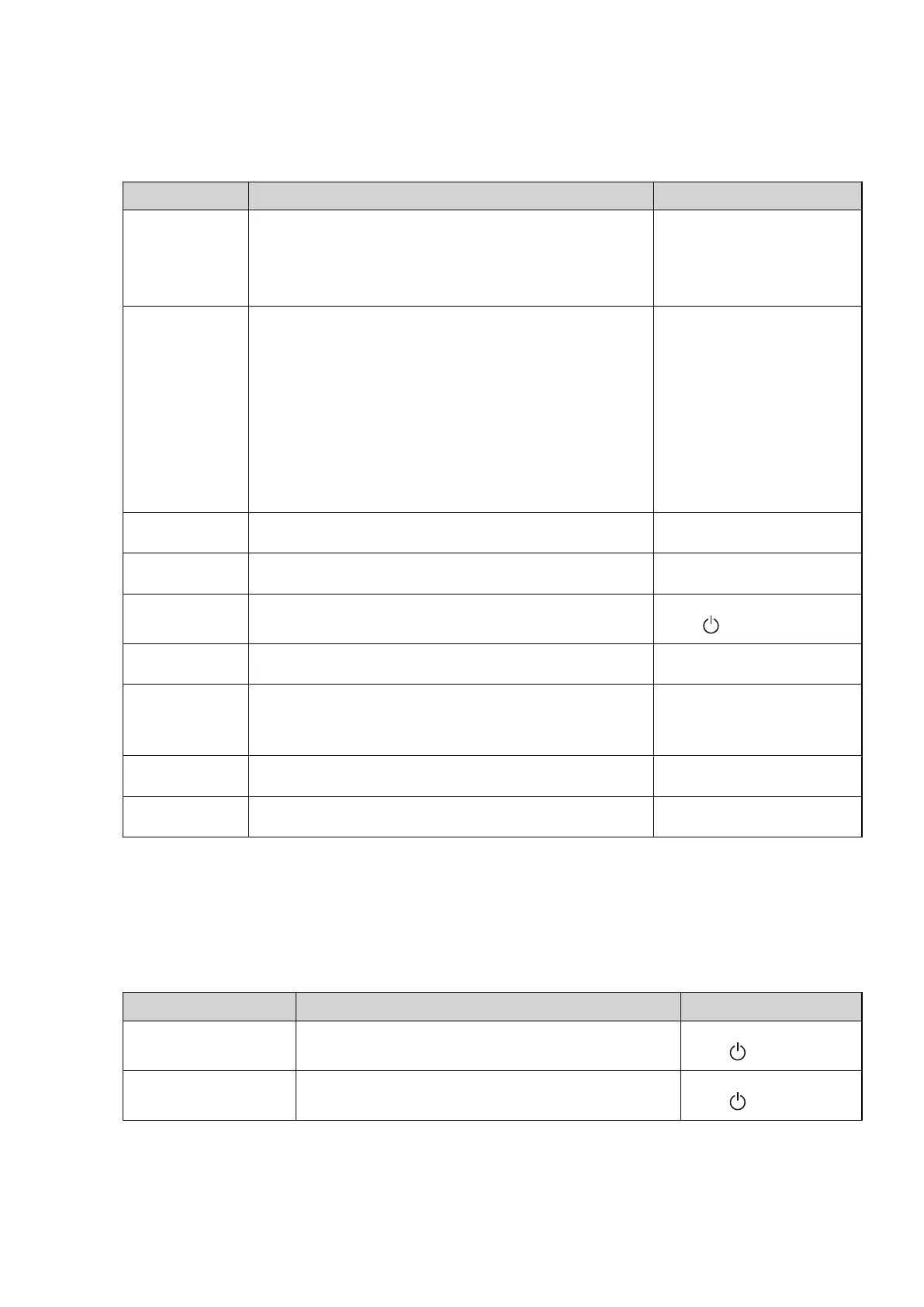
Table 22. Used to change settings for outdoor unit defrost.
Menu selection Meaning Factory setting
DEFR CURVE 0 Used to set the temperature of the heat pump’s brine return at
which defrosting should start, at 0°C outdoor temperature, using +
or -.
The graph can be changed up or down at 0°C outdoor temperature
in the display. See Important parameters for more information.
-10°C
(range: -15°C / -5°C)
DEFR CURVE -xx Used to set the temperature at which the heat pump's brine return
is to start a defrost, at the set outdoor temperature for OUTDOOR
STOP, using +or-.
The setting is made by reducing the OUTDOOR STOP value by this
value.
The number of degrees shown after DEFR CURVE in the display is
the set value for OUTDOOR STOP. The combined temperature is
shown in the top right corner of the display.
The graph can be changed up or down at the outdoor temperature
OUTDOOR STOP in the display. See Important parameters for more
information.
OUTDOOR STOP reduced by 4°C
(range: - 8°C / - 1°C)
DEFR TEMPERA-
TURE
The temperature shunted to the outdoor unit during a defrost. 15°C
(range: 13°C / 25°C)
STOP DEFR The temperature that the Brine In sensor must reach to complete a
defrost.
11°C
(range: 7°C / 12°C)
BELOW 5°C DEFR Safety defrosting occurs when the outdoor temperature has been
below 5°C for a set number of days, shunts +20°C for 10 minutes.
7D
(range: , 1D / 14D)
MIN TIME DEFR Minimum time between two defrosts in minutes. 45M
(range: 10M / 60M)
FAN START The fan starts when the temperature on the brine in sensor to the
heat pump reaches the set value.
If FAN START is set to ON, the fans starts and stops at the same time
as the compressor and the FAN STOP parameter is inactive.
-2°C
(range: ON, -5°C / FAN STOP-3°C)
FAN STOP The fan stops when the temperature on the brine in sensor to the
heat pump reaches the set value.
17°C
(range: FAN START +3°C / 30°C)
DEFR SENSOR Shows the actual temperature of the incoming air to the outdoor
unit.
9.7 Sub menu OPTIMUM
The menu applies to Opti with speed controlled circulation pumps and only appears if ON in SERVICE -> INSTALLA-
TION -> SYSTEM -> ADDITION -> OPTIMUM menu is selected.
Table 23. Used to change the circulations pumps’ operating settings.
Menu selection Meaning Factory setting
TEMP DIFF CIRC. Desired temperature difference between supply and return line
for the heating system.
8°C
(range: , 0°C / 15°C)
TEMP DIFF BRINE Desired temperature difference between supply and return line
for the brine system.
3°C
(range: , 0°C / 15°C)
60 – Installation instructions VMBMA1002
 Loading...


