6.3.2 Connection 230 V, 1-N
Circuit-breaker Terminal block heat pump
2 1
4 3
1L1 N2 PE1
2 1
4 3
2L1,
2L2
N3 PE42L1,
2L1
Figure 40. Connection 230V 1N
Incoming 230V heat pump
Incoming 230V immersion heater
6.3.3 Connection 230 V, 3-P
See country specific electrical instructions.
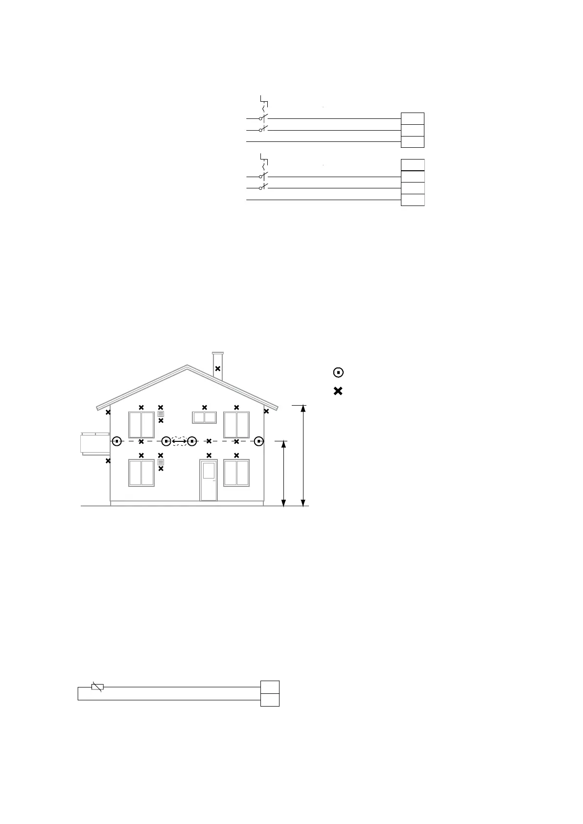
6.4 Position and connect outdoor sensors
Recommended location
Unsuitable location
•
Position the outdoor sensor on the north or north west side of the house.
•
For higher buildings, the sensor should be positioned between the second and third storeys. Its location must
not be completely protected from the wind but not in a direct draft. The outdoor sensor should not be placed
on reflective panel walls.
•
The sensor must be positioned at least 1 m from openings in the walls that emit hot air.
•
If the sensor cable is connected through a pipe, the pipe must be sealed so that the sensor is not affected by
outgoing air.
The outdoor sensor is connected by a two core cable. A maximum cable length of 50 m applies for a cross section
of 0.75 mm2. For greater lengths a cross section of 1.5 mm2 is used, up to a maximum of 120 m.
Then connect the sensor to the heat pump’s control system.
Figure 41. Connection outdoor sensor
40 – Installation instructions VMBMA1002
 Loading...


