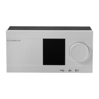
Instructions ECL Comfort 210 / 310, communication description
Danfoss District Energy VI.LG.V3.02 DEN-SMT/DK
12
6.3 RS-485 Bias/polarization
Biasing/polarization on the RS-485 Modbus network is necessary
for the bus to operate properly. It can be controlled by writing 0
(disable, this is default) / 1 (enable) to PNU 2049.
To simplify the installation, Danfoss recommends that
bias/polarization is implemented at the Modbus master.
See the section ‘Network layouts’
for further information about
biasing/polarization.
6.4 Mode and status
The mode parameters are located within the PNU range 4201 –
4203, i.e. 4201 is circuit 1, 4202 is circuit 2 and 4203 is circuit 3. The
mode can be used to control the ECL Comfort mode.
The status parameters are located within the PNU range 4211 –
4213, i.e. 4211 is circuit 1, 4212 is circuit 2 and 4213 is circuit 3. The
status indicates the current ECL Comfort status.
If one circuit is set to manual mode, it applies to all circuits (i.e. the
controller is in manual mode). When the mode is changed from
manual to another mode in one circuit, it also applies to all circuits
in the controller. The controller automatically reverts to the
previous mode if the information is available.
All output will follow the ECL manual output setting when in
manual mode.
The operating status will be read as 0 (setback) if the operating
mode is larger than 3.
Table 6-1:
Operating mode Code
Manual operation 0
Scheduled operation 1
Constant comfort temperature 2
Constant setback temperature 3
Frost protection/standby* 4
*
Standby and frost protection modes are not available in all
applications. In general the standby mode is available in cooling
applications instead of frost protection. Please read the
application instructions if in doubt.
Table 6-2:
Operating status Code
Setback 0
Pre-comfort 1
Comfort 2
Pre-setback 3
6.5 Heat curve
he heat curve has six points consisting of an outdoor temperature
coordinate and a flow temperature coordinate. The outdoor
temperature coordinates are not adjustable but the flow
temperature coordinates can be changed to give a flow
temperature that corresponds to the building’s thermodynamic
properties.
Table 6-3: Addresses for circuit 1 heat curve
Parameter PNU Default value
Slope (read only, scale = 10)
1
11175 10 ( = 1.0 )
Min. flow temperature 11177 10 °C
Max. flow temperature 11178 90 °C
Flow temp at -30 °C 11400 75 °C
Flow temp at -15 °C 11401 60 °C
Flow temp at -5 °C 11402 50 °C
Flow temp at 0 °C 11403 45 °C
Flow temp at 5 °C 11404 40 °C
Flow temp at 15 °C 11405 28 °C
1
Not all applications allow readout of this parameter

 Loading...


