Instructions ECL Comfort 210 / 310, communication description
6.14.2 Manual status (read only)
Manual status can be read in PNU 4020 – 4031 (Triac 1, Triac 2, ...,
relay 6).
For 3-point motorized control valve value output, the first PNU
holds the value, e.g. PNU 4020 for motorized control valve 1.
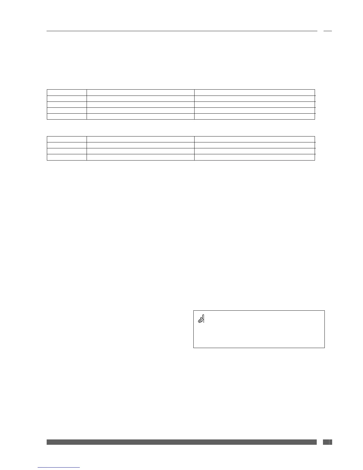
Value Display value Comment
0 AUTO Follows regulation or output override value
1 STOP The motorized control valve is not moved
2 CLOSE The motorized control valve is moved downwards
3 OPEN The motorized control valve is moved upwards
For relay output the following values apply:
Value Display value Comment
0 AUTO Follows regulation or output override value
1 OFF The pump is turned off
2 ON The pump is turned on
6.14.3 Output override
Output override can be used to control output in the ECL when it
is not in manual mode. If the ECL is in manual mode, the override
settings are not necessarily true, as it depends on the output the
application uses, and it can therefore not be relied upon to show
the actual status of the output. Output override can also be used
to control output that are not used in a specific application and
those output will therefore not be overruled if the ECL is in manual
mode!
Output override can be set in PNU 4060 – 4071 (ECL 310 Triac 1, …,
Triac 6, …, relay 1, …, relay 6).
PNU 4072 – 4075 (ECA 32 relay 1, …, relay 4)
Values are formatted equal to manual status.
6.15 Configurable input
The ECL 210 has two configurable input, i.e. S7-S8, whereas the
ECL 310 has four configurable input, i.e. S7-S10.
Sensor input S7 -S10 are configurable so that they can be
connected to different I/O types depending on application.
It is possible to set input options in order to accommodate various
output signal types from different hardware. To set a sensor input
to a specific type or input option, write the type (1-6) or option (0-
3) to the address as indicated in Table 6-10 or Table 6-11.
The tables are only guiding and some applications may have
limitations if the input are pre-configured. Please consult the
application instructions for further information.
Danfoss District Energy VI.LG.V3.02 DEN-SMT/DK
22
 Loading...