4 Manual RS8AX702 DKRCC.ES.R1.A1.02/ 520H4020 © Danfoss 01-2011 EKC 347
Survey of functions
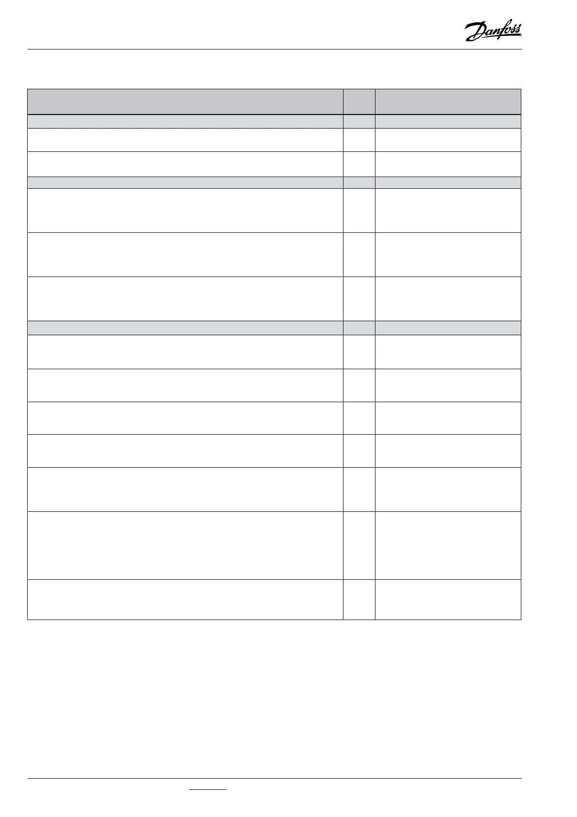
Function Para-
meter
Parameter by operation via
data communication
Normal display Level control
The liquid level is indicated in %
The % value is calculated on the basis of the input signal and the denition in ”o31”.
- Liquid level
The valve’s actual opening degree can be displayed by giving the lower button a brief
push (1s). Cf. also o17.
- OD %
Reference
Set point
Regulation is based on the set value provided that there is no external contribution
(o10).
(Push both buttons simultaneously to set the setpoint).
- SP Liquid Level
External contribution to the reference
This setting determines how large a contribution is to be added to the set reference
when the input signal is max (20 mA or 10 V. Cf. also o10).
The value is set in %-points.
r06 r06 Ext. Ref.oset
Start/stop of regulation
With this setting the level regulation can be started and stopped. Start/stop of level
regulation can also be performed with the external contact function. Regulation is
stopped if just one of them is OFF.
r12 r12 Main Switch
Alarm Level Alarms
The controller can give alarm in dierent situations.
When there is an alarm the three lowest LED’s at the front of the controller will ash,
and the alarm relay is cut in
Limit for upper level
Here you set the limit value for the upper level indication. The value is set in %. The
relay for the upper level will become activated when the level exceeds the set value.
A01 A01 Upper Dev.
Limit for lower level
Here you set the limit value for the lower level indication. The value is set in %. The re-
lay for the lower level will become activated when the level drops below the set level.
A02 A02 Lower Dev.
Time delay for upper level limit
When the limit value is exceeded a timer function will start. The relay will not become
activated until the set time delay has been passed. The time delay is set in seconds.
A03 A03 Upper Delay
Delay for lower limit level
When the limit value is exceeded a timer function will start.The relay will not become
activated until the set time delay has been passed.
The time delay is set in seconds.
A15 A15 Lower Delay
Limit for alarm level
An alarm level can be set which when passed will activate the alarm relay- The value is
set in %. Cf. also the denition in A18.
If the limit alarm (A3) is not required, it can be avoided by means of the following set-
ting in A16:
100 : If the rising level denition has been chosen. (A18=0 or 2)
0: If the falling level denition has been chosen. (A18=1 or 3)
A16 A16 Limit Alarm
Time delay for alarm level
When the alarm level is exceeded a timer function will start. The relay will not become
activated until the set time delay has been passed.
The time delay is set in seconds.
A17 A17 Limit Delay
 Loading...