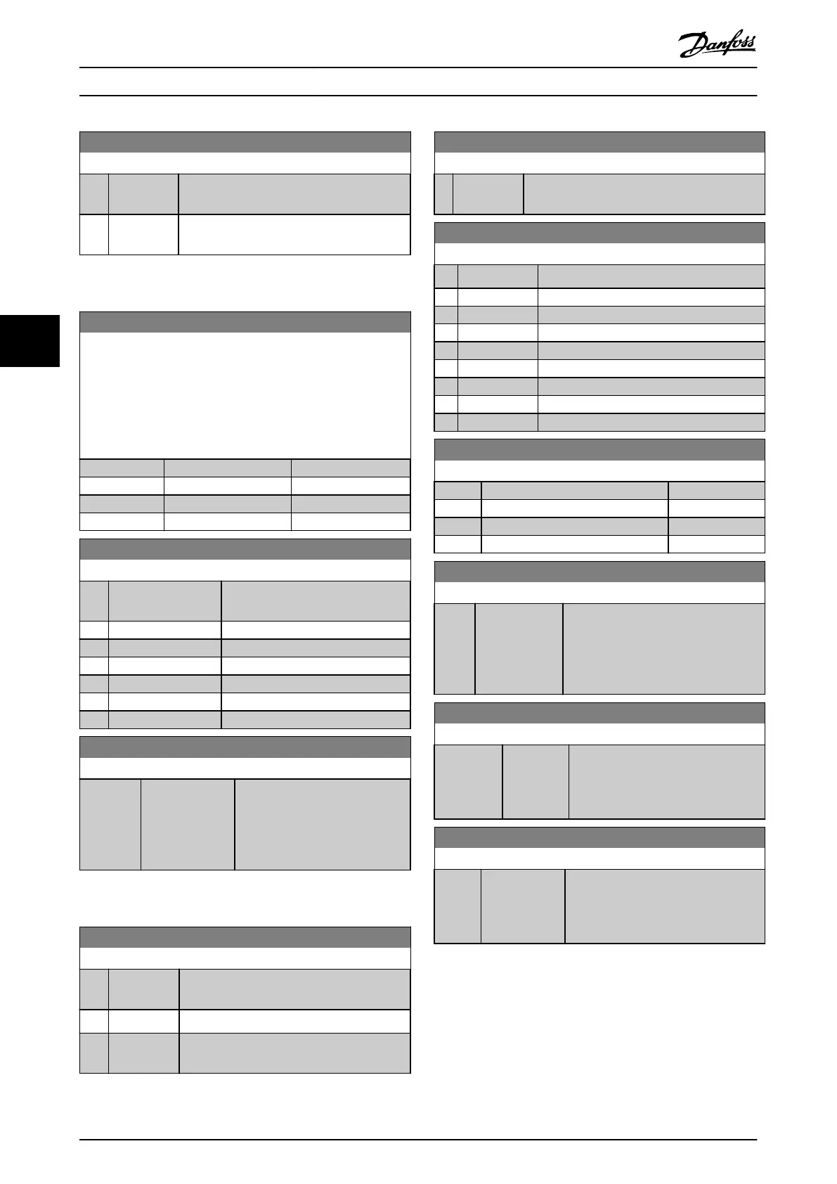
8-07 Diagnosis Trigger
Option: Function:
[1] Trigger on
alarms
Extended diagnosis data is sent when 1 or
more alarms appear.
[2] Trigger
alarm/warn.
Extended diagnosis data is sent if 1 or more
alarms/warnings appear.
5.1.2 8-1* Ctrl. Word Settings
8-10 Control Word Prole
Select the interpretation of the control and status words
corresponding to the installed eldbus. Only the selections valid
for the eldbus installed are visible in the LCP display.
For guidelines in selection of [0] Frequency converter prole and
[1] PROFIdrive prole, refer to the design guide for the frequency
converter.
Option: Function:
[0] * FC prole
[1] PROFIdrive prole
[5] ODVA
[7] CANopen DSP 402
8-14 Congurable Control Word CTW
Option: Function:
Selection of control word bit 10 if it
is active low or active high.
[0] None
[1] * Prole default
[2] CTW Valid, active low
[4] PID error inverse
[5] PID reset I part
[6] PID enable
8-19 Product Code
Range: Function:
Size
related*
[0 -
2147483647]
Select 0 to read out the actual
eldbus product code according
to the mounted eldbus option.
Select 1 to read out the actual
vendor ID.
5.1.3 8-3* FC Port Settings
8-30 Protocol
Option: Function:
Select the protocol for the integrated RS485
port.
[0] * FC Communication according to the FC protocol.
[2] Modbus RTU Communication according to the Modbus
RTU protocol.
8-31 Address
Range: Function:
1* [ 0.0 - 247 ] Enter the address for the RS485 port. Valid
range: 1–126 for FC-bus or 1–247 for Modbus.
8-32 Baud Rate
Option: Function:
Select the baud rate for the RS485 port.
[0] 2400 Baud
[1] 4800 Baud
[2] 9600 Baud
[3] 19200 Baud
[4] 38400 Baud
[5] 57600 Baud
[6] 76800 Baud
[7] 115200 Baud
8-33 Parity / Stop Bits
Option: Function:
[0] * Even Parity, 1 Stop Bit
[1] Odd Parity, 1 Stop Bit
[2] No Parity, 1 Stop Bit
[3] No Parity, 2 Stop Bits
8-35 Minimum Response Delay
Range: Function:
0.01 s* [ 0.0010 - 0.5
s]
Specify the minimum delay time
between receiving a request and
transmitting a response. This is used for
overcoming modem turn-around
delays.
8-36 Maximum Response Delay
Range: Function:
Size related* [ 0.1 - 10.0
s]
Specify the maximum allowed delay
time between receiving a request and
transmitting the response. If this time
is exceeded, no response is returned.
8-37 Maximum Inter-char delay
Range: Function:
0.025 s* [0.025 - 0.025
s]
Specify the maximum delay time
between 2 characters in a message.
Exceeding this delay time causes the
message to be discarded.
Parameters EtherNet/IP
22 Danfoss A/S © 06/2016 All rights reserved. MG07H102
55
 Loading...


