L1
L2
L3
3 Phase
power
input
PE
PE
+10 V DC
0-10 V DC-
0-10 V DC-
50 (+10 V OUT)
54 (A IN)
53 (A IN)
55 (COM A IN/OUT)
0/4-20 mA
0/4-20 mA
42 0/4-20 mA A OUT / DIG OUT
45 0/4-20 mA A OUT / DIG OUT
18 (DIGI IN)
19 (DIGI IN)
27 (DIGI IN)
29 (DIGI IN)
12 (+24 V OUT)
24 V (NPN)
20 (COM D IN)
O V (PNP)
24 V (NPN)
O V (PNP)
24 V (NPN)
O V (PNP)
24 V (NPN)
O V (PNP)
Bus ter.
Bus ter.
RS-485
Interface
RS-485
(N PS-485) 69
(P RS-485) 68
(Com RS-485 ) 61
(PNP)-Source
(NPN)-Sink
ON=Terminated
OFF=Unterminated
ON
1 2
240 V AC 3 A
Not present on all power sizes
Do not connect shield to 61
01
02
03
relay1
relay2
UDC+
UDC-
Motor
U
V
W
130BD467.10
06
05
04
240 V AC 3 A
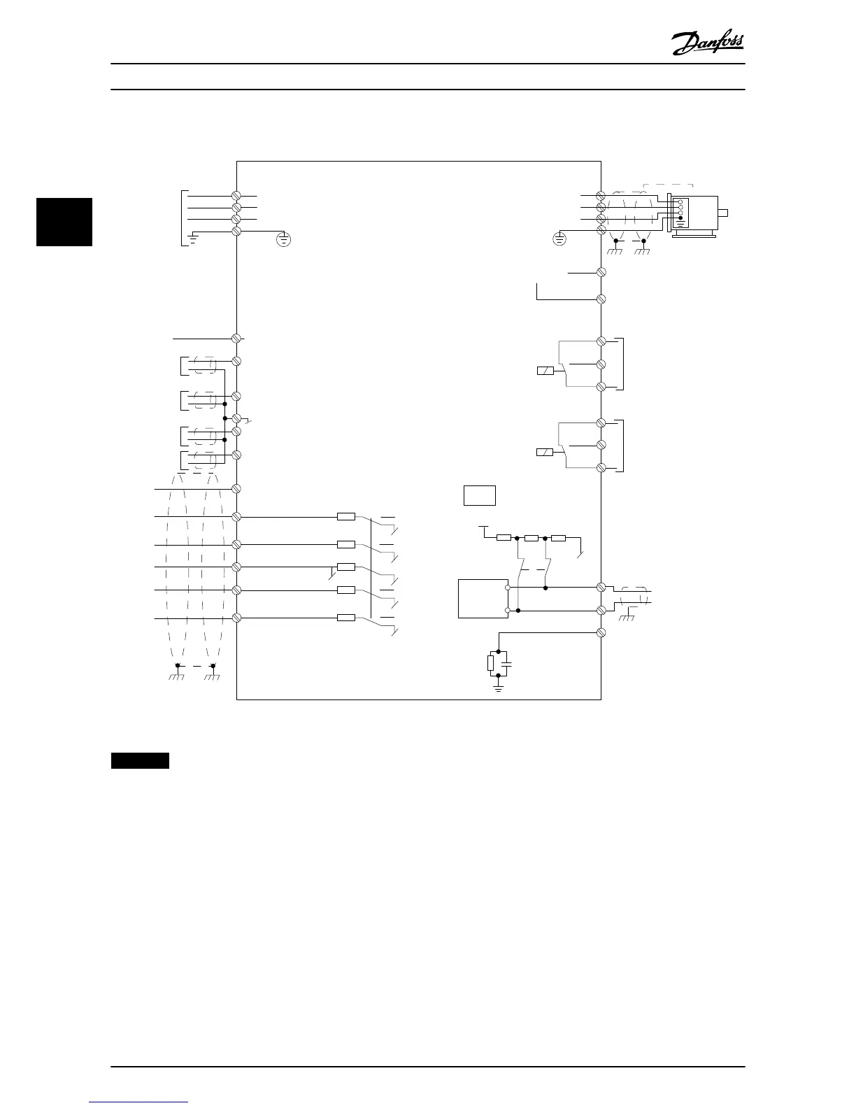
Illustration 3.24 Basic Wiring Schematic Drawing
NOTICE
There is no access to UDC- and UDC+ on the following units:
IP20, 380–480 V, 30–90 kW (40–125 HP)
IP20, 200–240 V, 15–45 kW (20–60 HP)
IP20, 525–600 V, 2.2–90 kW (3–125 HP)
IP54, 380–480 V, 22–90 kW (30–125 HP)
Installation Quick Guide
22 Danfoss A/S © 08/2014 All rights reserved. MG18A602
33

 Loading...


