Home
Danfoss
Media Converter
FC 101
Danfoss FC 101 User Manual
4
of 1
of 1 rating
58 pages
Give review
Manual
Specs
To Next Page
To Next Page
To Previous Page
To Previous Page
4.2
Set-up Wizard
The
built-in
wizard
menu
guides
the
installer
through
the
set-up
of
the
frequency
converter
in
a
clear
and
structured
manner
for
open-loop
and
closed-loop
applications
and
quick
motor
settings.
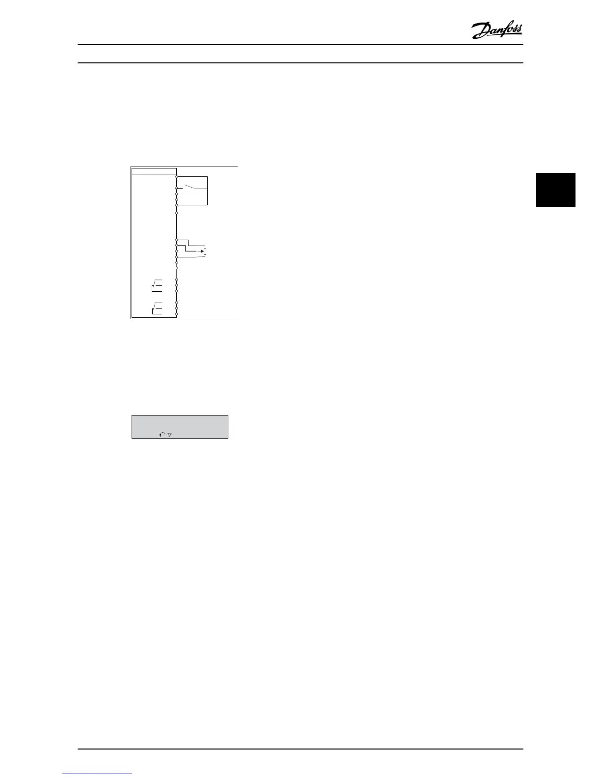
FC
+24V
DIG IN
DIG IN
DIG IN
DIG IN
COM DIG IN
A OUT / D OUT
A OUT / D OUT
18
19
27
29
42
55
50
53
54
20
12
01
02
03
04
05
06
R2
R1
+
-
0-10V
Start
+10V
A IN
A IN
COM
130BB674.10
45
Reference
Illustration
4.2
Frequency
Converter
Wiring
The
wizard
will
initially
be
shown
after
power-up
until
any
parameter
has
been
changed.
The
wizard
can
always
be
accessed
again
through
the
quick
menu.
Press
[OK]
to
start
the
wizard.
Press
[Back]
to
return
to
the
status
screen.
130BB629.10
Press OK to start
Wizard
Push Back to skip it
Setup 1
Illustration
4.3
Start-up/Quit
Wizard
Programming
Quick Guide
MG18A602
Danfoss A/S © 08/2014 All rights reserved.
25
4
4
26
28
Table of Contents
Default Chapter
3
Table of Contents
3
1 Introduction
5
Purpose of the Quick Guide
5
Additional Resources
5
Document and Software Version
5
Certificates and Approvals
5
Disposal
5
2 Safety
6
Safety Symbols
6
Qualified Personnel
6
Motor Thermal Protection
7
3 Installation
8
Mechanical Installation
8
Side-By-Side Installation
8
Frequency Converter Dimensions
9
Electrical Installation
11
Electrical Installation in General
11
IT Mains
12
Connecting to Mains and Motor
13
Fuses and Circuit Breakers
19
EMC-Correct Electrical Installation
22
Control Terminals
23
Electrical Wiring
24
Acoustic Noise or Vibration
25
4 Programming
26
Local Control Panel (LCP)
26
Set-Up Wizard
27
Parameter List
39
5 Warnings and Alarms
42
6 Specifications
44
Mains Supply
44
3X200-240 V AC
44
3X380-480 V AC
45
3X525-600 V AC
49
EMC Emission Test Results
50
Special Conditions
51
Derating for Ambient Temperature and Switching Frequency
51
Derating for Low Air Pressure and High Altitudes
51
General Technical Data
52
Protection and Features
52
Mains Supply (L1, L2, L3)
52
Motor Output (U, V, W)
52
Cable Lengths and Cross Sections
52
Digital Inputs
53
Analog Inputs
53
Analog Output
53
Digital Output
53
Control Card, RS-485 Serial Communication
54
Control Card, 24 V DC Output
54
Relay Output
54
Control Card, 10 V DC Output 1)
54
Ambient Conditions
55
Index
56
Other manuals for Danfoss FC 101
Design Guide
124 pages
4
Based on 1 rating
Ask a question
Give review
Questions and Answers:
Need help?
Do you have a question about the Danfoss FC 101 and is the answer not in the manual?
Ask a question
Danfoss FC 101 Specifications
General
Model
FC 101
Manufacturer
Danfoss
Protection Class
IP20
Relative Humidity
95% (non-condensing)
Communication Interface
RS-485
Related product manuals
Danfoss FC 100 Series
149 pages
Danfoss VLT Series FC 102
18 pages
Danfoss FC 302
77 pages
VLT Micro Drive FC 51 Series
73 pages
Danfoss VLT PROFIBUS DP MCA 101
64 pages
Danfoss FCM 300 Series
108 pages
VLT HVAC Basic Drive FC 101
62 pages
Danfoss 102
94 pages
Danfoss VLT 5152
240 pages
Danfoss VLT 5052
240 pages
Danfoss VLT Micro
21 pages
Danfoss VLT AQUA Drive Series
204 pages