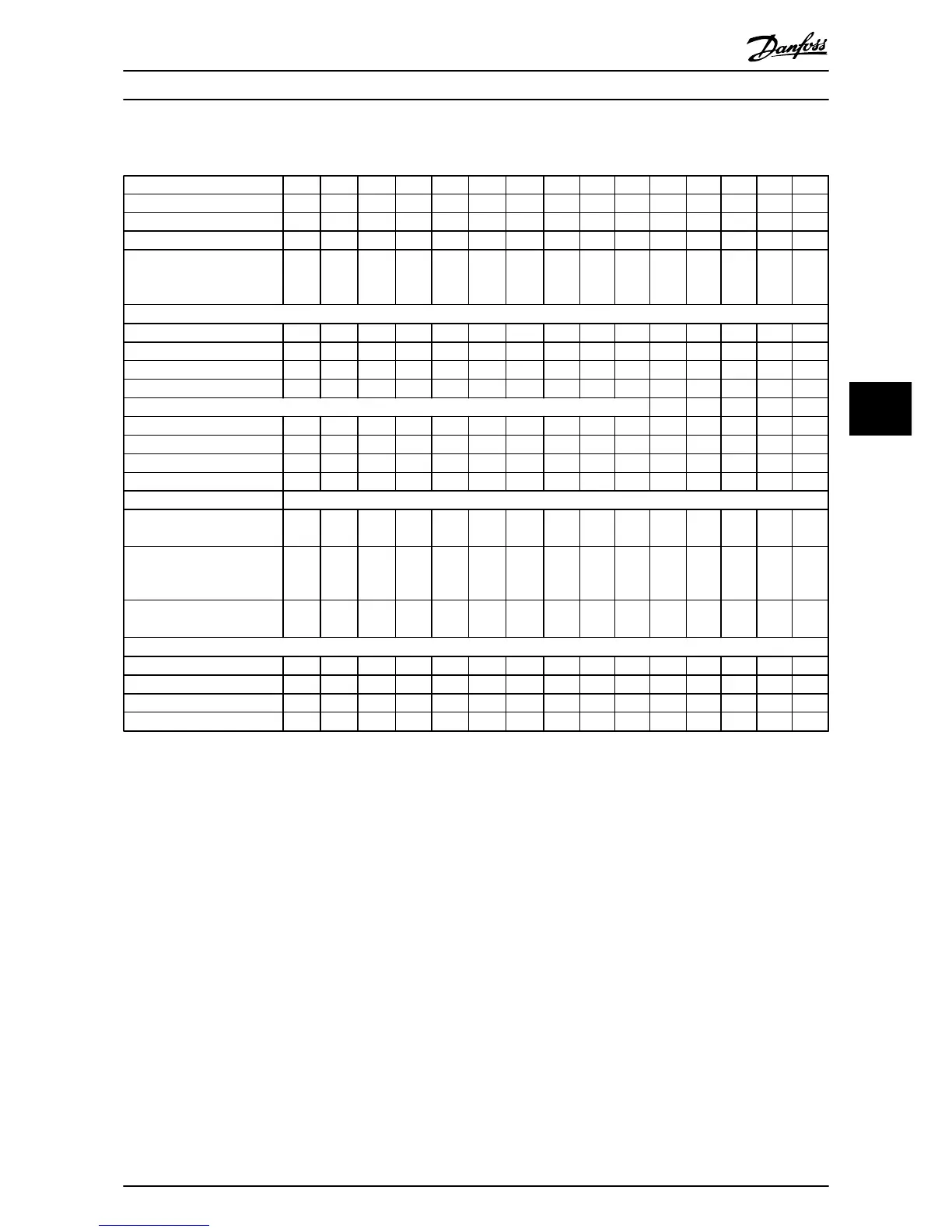
6.1.3 3x525–600 V AC
Frequency converter P2K2 P3K0 P3K7 P5K5 P7K5 P11K P15K P18K P22K P30K P37K P45K P55K P75K P90K
Typical shaft output [kW] 2.2 3.0 3.7 5.5 7.5 11.0 15.0 18.5 22.0 30.0 37 45.0 55.0 75.0 90.0
Typical shaft output [HP] 3.0 4.0 5.0 7.5 10.0 15.0 20.0 25.0 30.0 40.0 50.0 60.0 70.0 100.0 125.0
IP20 frame H9 H9 H9 H9 H9 H10 H10 H6 H6 H6 H7 H7 H7 H8 H8
Maximum cable size in
terminals (mains, motor)
[mm
2
(AWG)]
4 (10) 4 (10) 4 (10) 4 (10) 4 (10) 10 (8) 10 (8) 35 (2) 35
(2)
35
(2)
50 (1) 50
(1)
50 (1) 95
(0)
120
(4/0)
Output current - 40 °C (104 ° F) ambient temperature
Continuous (3x525–550 V) [A] 4.1 5.2 6.4 9.5 11.5 19.0 23.0 28.0 36.0 43.0 54.0 65.0 87.0 105.0 137.0
Intermittent (3x525–550 V) [A] 4.5 5.7 7.0 10.5 12.7 20.9 25.3 30.8 39.6 47.3 59.4 71.5 95.7 115.5 150.7
Continuous (3x551–600 V) [A] 3.9 4.9 6.1 9.0 11.0 18.0 22.0 27.0 34.0 41.0 52.0 62.0 83.0 100.0 131.0
Intermittent (3x551–600 V) [A] 4.3 5.4 6.7 9.9 12.1 19.8 24.2 29.7 37.4 45.1 57.2 68.2 91.3 110.0 144.1
Maximum input current
Continuous (3x525–550 V) [A] 3.7 5.1 5.0 8.7 11.9 16.5 22.5 27.0 33.1 45.1 54.7 66.5 81.3 109.0 130.9
Intermittent (3x525–550 V) [A] 4.1 5.6 6.5 9.6 13.1 18.2 24.8 29.7 36.4 49.6 60.1 73.1 89.4 119.9 143.9
Continuous (3x551–600 V) [A] 3.5 4.8 5.6 8.3 11.4 15.7 21.4 25.7 31.5 42.9 52.0 63.3 77.4 103.8 124.5
Intermittent (3x551–600 V) [A] 3.9 5.3 6.2 9.2 12.5 17.3 23.6 28.3 34.6 47.2 57.2 69.6 85.1 114.2 137.0
Maximum mains fuses
See chapter 3.2.4 Fuses and Circuit Breakers
Estimated power loss [W],
best case/typical
1)
65 90 110 132 180 216 294 385 458 542 597 727 1092 1380 1658
Weight enclosure IP54 [kg
(lb)]
6.6
(14.6)
6.6
(14.6)
6.6
(14.6)
6.6
(14.6)
6.6
(14.6)
11.5
(25.3)
11.5
(25.3)
24.5
(54)
24.5
(54)
24.5
(54)
36.0
(79.3)
36.0
(79.3)
36.0
(79.3)
51.0
(112.
4)
51.0
(112.
4)
Efficiency [%],
best case/typical
2)
97.9 97 97.9 98.1 98.1 98.4 98.4 98.4 98.4 98.5 98.5 98.7 98.5 98.5 98.5
Output current - 50 °C (122 °F) ambient temperature
Continuous (3x525–550 V) [A] 2.9 3.6 4.5 6.7 8.1 13.3 16.1 19.6 25.2 30.1 37.8 45.5 60.9 73.5 95.9
Intermittent (3x525–550 V) [A] 3.2 4.0 4.9 7.4 8.9 14.6 17.7 21.6 27.7 33.1 41.6 50.0 67.0 80.9 105.5
Continuous (3x551–600 V) [A] 2.7 3.4 4.3 6.3 7.7 12.6 15.4 18.9 23.8 28.7 36.4 43.3 58.1 70.0 91.7
Intermittent (3x551–600 V) [A] 3.0 3.7 4.7 6.9 8.5 13.9 16.9 20.8 26.2 31.6 40.0 47.7 63.9 77.0 100.9
Table 6.6 3x525–600 V AC, 2.2–90 kW (3-125 HP), Enclosure Type H6–H10
1) Applies for dimensioning of frequency converter cooling. If the switching frequency is higher than the default setting, the power losses may
increase. LCP and typical control card power consumptions are included. For power loss data according to EN 50598-2, refer to
www.danfoss.com/vltenergyefficiency.
2) Efficiency measured at nominal current. For energy efficiency class, see chapter 6.4.13 Ambient Conditions. For part load losses, see
www.danfoss.com/vltenergyefficiency.
Specifications Quick Guide
MG18A602 Danfoss A/S © 08/2014 All rights reserved. 47
6 6

 Loading...


