FC 300 Instruction Manual
How to Program
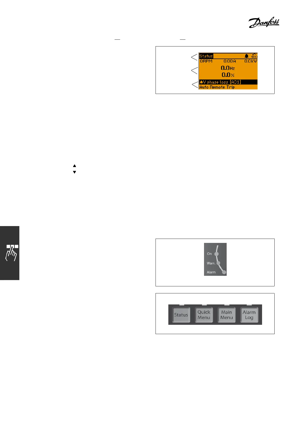
Top section shows up to 2 measurements
in normal operating status.
ThetoplineintheMiddle section shows up to
5 measurements with related units, regardless of
status (except in the c ase of alarm/warning).
Bottom section always shows the state of the
adjustable frequency drive in Status mode.
130BP074.10
Top section
Middle section
Bottom section
The Active Set-up ( selected as the Active Set-up in par. 0-10) is shown. When programming another Set-up
other than the Active Set-up, the number of theprogrammedSet-upappearstotheright.
Display Contrast Adjustment
Press [status] and [
] for darker display
Press [status] and [
]forbrighterdisplay
Most FC 300 parameter set-ups can be changed immediately via the control panel, unless a password
has been created via par. 0-60 Main Menu Password or via par. 0-65 Quick Menu Password.
LEDs:
If certain threshold values are exceeded, the alarm and/or warning L ED light(s) up. A
status and alarm text appear on the c ontrol panel.
The on LED is ac tivated when the adjustable frequency drive receives line voltage or via a DC b us
terminal or 24 V external supply. At the same time, the back light is on.
• Green LED/On: Control section is wo rking.
• Yellow LED/Warn.: Indica tes a warning.
• Flashing Red L ED/Alarm: Indicates an alarm.
130BP040.10
LCP keys
The control keys are divided into functions. The
keys below the display and LED S are used for
parameter Set-up
, including choice of d isplay
indication during normal operation.
130BP045.10
[Status] indicates the status of the adjustable frequency drive and/or the motor. You can
choose between 3 different readouts by pressing the [Status] key:
36
MG.33.A4.22 - VLT is a registered Danfoss trademark

 Loading...


