FC 300 Instruction Manual
General Specifications
Control card, RS 485 serial communication:
Terminal number ................................................................................... 68 (TX+, RX+), 69 (TX-, RX-)
Terminal number 61 ....................................................................... Common for terminals , 68 and 69
The RS 485 serial communication is functionally separated and galvanically is o-
lated from the supplier voltage (PELV).
Control card, USB serial communication:
USB standard ............................................................................................................. 2 (low speed)
USB plug .................................................................................................... USB type B "device" plug
Connection to PC is done via a standard host/device USB cable.
The USB connection is galvanically isolate d from the supply voltage (PELV) and other high-voltage terminals.
Relay outputs
Programmable relay outputs ............................................................................. FC 301: 1 / FC 302: 2
Terminal number, power card ...................................... 1-3 (break), 1-2 (make), 4-6 (break), 4-5 (make)
Max. terminal load (AC) on 1-3 (break), 1-2 (make), 4-6 (break) power card ...................... 240 V AC, 2 A
Max. terminal load (AC) on 4-5 (make) power card ......................................................... 400 V AC, 2 A
Min. terminal l oad on 1-3 (break), 1-2 (make), 4-6 (break), 4-5 (make) power
card ................................................................................................ 24 V DC 10 mA, 24 V AC 100 mA
Environment according to EN 60664-1 ................................. overvoltage category 111/pollution degree 2
The relay contacts are galvanically isolated from the rest of the circuit b y reinforced isolation (SELV).
Cable lengths and cross -sections:
Max. motor cable length, shielded/armored ..................... FC 301: 164 ft (50 m) / FC 302: 492 ft (150 m)
Max. motor cable length, non-shielded/unarmored ........... FC 301: 246 ft (75 m) / FC 302: 984 ft (300 m)
Max. cross-section to m otor, mains, load sharing and brake (see section Electrical D ata in the
FC 300 Design Guide MG.33.BX.YY for more information), (0.34 HP - 10 HP / 0.25 kW - 7.5
kW) ...................................................................................................... 0.006 in.
2
(4 mm
2
)/10AWG
Maximum cross-section to control wires, rigid wire ................................................................................
0.002 in.
2
(1.5 mm
2
)/16 AWG (2 x 0.001 in.
2
(2 x 0.75 mm
2
))
Maximum cro ss-se ction to control ca ble s, flexible cable .............................. 0.0015 in.
2
(1 mm
2
)/18 AWG
Maximum cro ss-se ction to control cable s, cable with enclosed core ............ 0.0008 in.
2
(0.5 mm
2
)/20 A
WG
Minimum cross-section to control wires ............................................................. 0.0004 in.
2
(0.25 mm
2
)
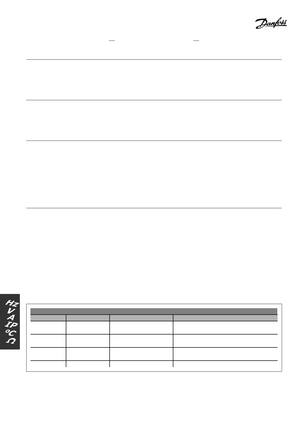
Cable lengths a nd RFI performance
FC 30x Filter Supply voltage RFI compliance at m ax. motor cable lengths
FC 301
FC 302
With A2 filter 200 - 240 V / 380 - 500 V /
380 - 480 V
<16 ft (5 m) EN 55011 Group A2
FC 301 With A1/B 200 - 240 V / 380 - 480 V <131 ft (40 m) EN 55011 Group A1
<33 ft (10 m) EN 55011 Group B
FC 302 With A1/B 200 - 240 V / 380 - 500 V <492 ft (150 m) EN 55011 Group A1
<131 ft (40 m ) EN 55011 Group B
FC 302 No RFI filter 550 - 600 V Not compliant with EN 55011
In certain instances, shorten the motor cable to c omply with
EN 55011 A1 and EN 55011 B.
64
MG.33.A4.22 - VLT is a registered Danfoss trademark

 Loading...


