Quick Start Guide | ICM/ICAD Motorized Valves - Installation, Programming, and Troubleshooting
© Danfoss | DCS (MWA) | 2016.07
DKRCI.EI.HT0.B3.22 | 520H4763 | 7
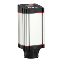
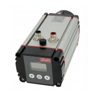
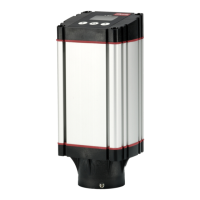
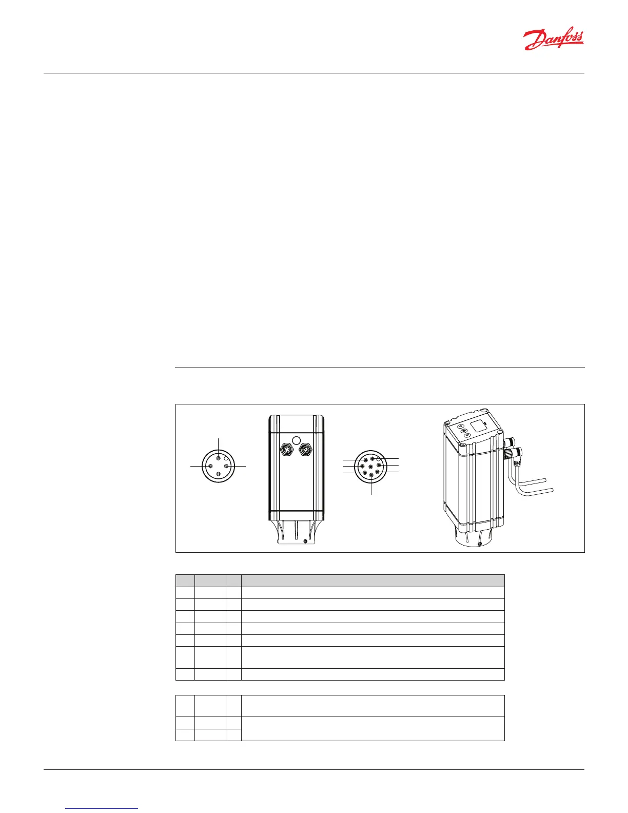
Wiring the ICAD actuator There are two cables which are connected to the ICAD motor with M12 connectors:
Supply voltage is galvanically isolated from input and output wires
Supply Voltage Fail Safe Supply
24 VDC + 10%/-15% Min. 19 VDC
Load ICAD 600A 1.2 A ICAD 600A 1.2 A
ICAD 1200A 2.0 A ICAD 1200A 2.0 A
Analog Input – Current or Voltage Analog Output
Current 0/4 – 20 mA 0/4 – 20 mA
Load: 200Ώ Load: ≤ 250 Ώ
Voltage 0/2 – 10 VDC
Load: 10k Ώ
Digital Input – Digital On/O input by means of voltfree contact with gold-plated contacts recommended
Voltage Input Used
ON: contact impedance < 50 Ώ
OFF: contact impedance > 100 k Ώ
Digital Output: 3 pcs. NPN transistor output
External Supply: 5 – 24 VDC (same supply as for ICAD can be used but note that galvanically
isolated system will be spoiled.
Output Load: 50 Ώ
Load Max. 50 mA
Electrical data
Communication connector / cable
Ref. Color Description
A Black – Common Alarm
B Brown – ICM fully open
C Red – ICM fully closed
D Orange – GND ground
E Yellow + 0/4 - 20 mA Input*
F Green +
0/2 - 10 V Input. Also used with GND (orange wire) as a digital input #1 for
on-o operation or oating 3-point control
G Blue + 0/4 - 20 mA Output*
Power connector/cable (3 wires)
I Black +
Fail safe supply
Battery / UPS (uninterruptable power supply) 19 V d.c.
II White +
Supply voltage
24 V d.c.
III Brown –
}
Digital
Ouput
I
II
C
D
E
B
A
G
F
4 pin male connector 8 pin male connector
* If using oating 3-point control (parameter i02=3) then wire colors yellow and blue are combined to make the 2nd digital input
 Loading...