P107 816E
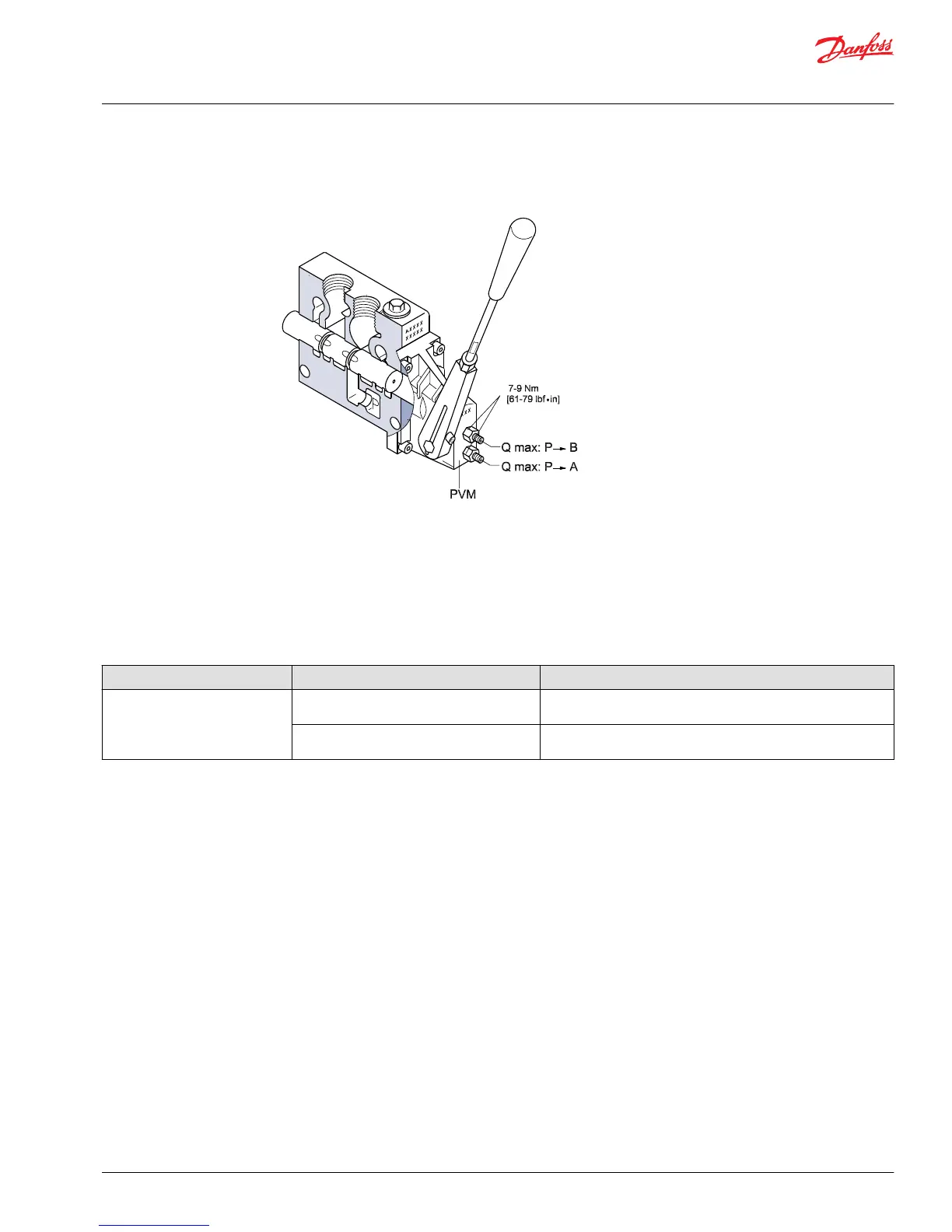
For standard mount, top adjusting screw is B
and bottom adjusting screw is A
PVM module
Description: Manual control lever.
Location: Mounted on either end of the PVB main spool.
Function: Manual override capable of limiting the stroke of the main spool, and is used to center the
spool in neutral.
Failure mode Cause Corrective action
Leaking externally between PVM
and PVB
Back pressure is exceeding 40 Bar [580 PSI] on
tank line
Replace PVM module, seals, and lower tank port pressure
T0 port not connected to tank or restricted or
blocked
Connect to tank, remove restriction, and remove blockage
Service Manual
PVG 32 Proportional Valve Group
PVG 32 Component Troubleshooting
©
Danfoss | February 2017 11039167 | AX00000031en-US0301 | 33
 Loading...