42 MG.30.A7.02 - VLT
®
is a registered Danfoss trademark
Mechanical installation
The front door to VLT
®
3032-3052, 230 V,
and VLT
®
3060-3250 has hinges on the
left-hand side.
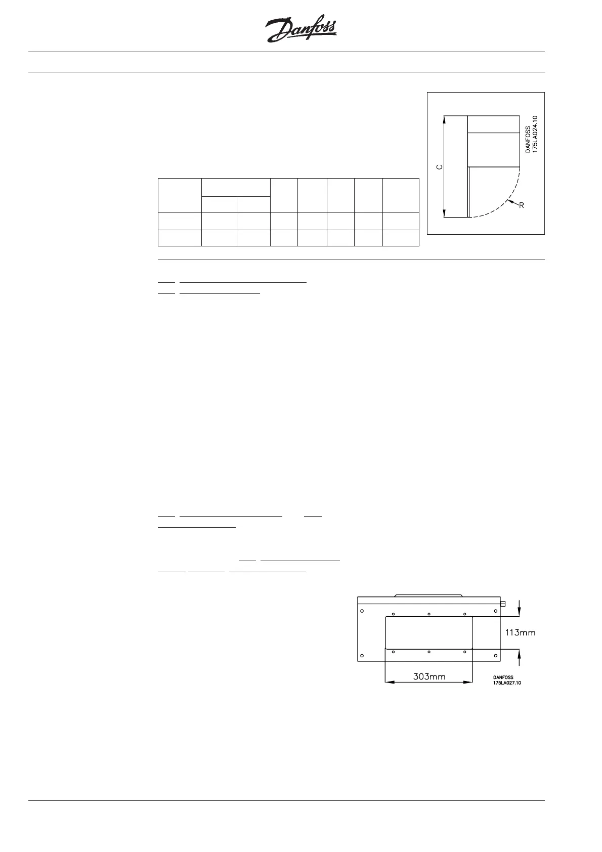
The table below shows the door radius
and the distance necessary from the
installation surface to be able to open the
door without difficulty.
VLT
®
3032-3052, 230 V,
VLT
®
3060-3250
VLT-type 3032-52, 230 V, 3100 3125 3150 3200 3250
3060 3075
C [mm] 846 846 894 894 894 1008 1008
R [mm] 505 505 513 513 513 513 513
It is recommended that the cables be lead
through the base, but the sides can also
be used.
The plate in the right-hand side of the
VLT
®
enclosure can be removed, and the
hole can be used for cable lead-through if
an extra enclosure or an IP 54 RFI module
is required. If one of these modules is to
be used, the right-hand side of the VLT
®
enclosure may not be bored for other
cables.
The VLT
®
enclosure is made of steel. To
avoid metal flakes flying into the VLT
®
’s
electronics, cable holes should not be
bored until the unit has been vertically
installed.
The drawing below shows the VLT
®
types
3060-3250 seen from the bottom with the
removable base plate.
VLT
®
types 3002-3008, 400/500 V, and
VLT
®
3002-3004, 200 V, with IP 54 en-
closure have a plastic base with holes
marked for cable unions.
Note that for the above VLT
®
s for 200 V
and 500 V (UL-approved) a metallic
bonding plate is included in the plastic
base. The metal plate is used to terminate
cable conductor or armouring. See the
information on p. 148 concerning connec-
tion of the bonding plate when IP 00 VLT
®
s
are converted to IP 21 enclosure with UL
approval.
The cable unions mechanically support the
cables for IP 21/54 enclosure. For the
IP 00 version, the cables must be relieved
by other means (cable stirrups). The
cables end in removable plugs.
VLT
®
3011-3052, 400/500 V, and VLT
®
3006-3022, 200 V, have a metal base with
cut-outs for cable lead-through.
The bottom of the VLT
®
types 3032-3052,
230 V, and VLT
®
types 3060-3250 has a
plate mounted with 6 cross-head screws.
The plate can be removed to ease installa-
tion of the cable unions. After cable lead-
through has been completed, the plate
must be screwed back in place to ensure
correct IP enclosure grade and cooling.
Cable access:
Artisan Technology Group - Quality Instrumentation ... Guaranteed | (888) 88-SOURCE | www.artisantg.com

 Loading...


