VLT
®
5000 Series
the process regulator will take long to regulate
if an error has occurred.
419 Speed PID differential time
(SPEED DIFF. TIME)
Value:
0.00 (OFF) - 200.00 ms
✭ 30 ms
Function:
The differentiator does not react to a constant
error. It only provides a gain if the error changes.
The quicker the error changes, the stronger the
gain from the differentiator will be.
The gain is proportional to the speed at
which errors change.
Used together with Speed control, closed
loop (parameter 100).
Description of choice:
Select the desired gain limit.
420 Speed PID D-gain limit
(SPEED D-GAIN LIMIT)
Value:
5.0 - 50.0
✭ 5.0
Function:
It is possible to set a limit for the gain provided by the
differentiator. Since the D-gain increases at higher
frequencies, limiting the gain may be useful.
This enables obtaining a pure D-link at low frequencies
and a constant D-link at higher frequencies.
Used together with Speed control, closed
loop (parameter 100).
Description of choice:
Select the desired gain limit.
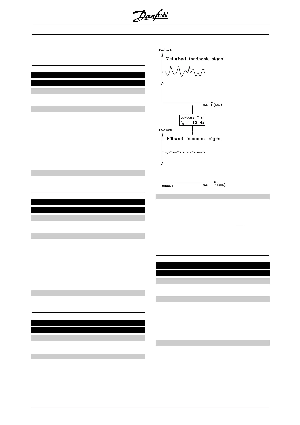
421 Speed PID lowpass filter time
(SPEED FILT. TIME)
Value:
5 - 200 ms
✭ 10 ms
Function:
Oscillations on the feedback signal are dampened
by a lowpass filter so as to reduce their influence on
control. This might be an advantage, e.g. if there is a
great amount on noise on the system. See drawing.
Used together with Speed control, closed loop and
Torque control, speed feedback (parameter 100).
Description of choice:
Ifatimeconstant(τ) e.g. of 100 ms is programmed,
the cut-off frequency for the lowpass filter will be 1/0.1
= 10 RAD/sec., corresponding to (10/2 x π)=1.6Hz.
This means that the PID regulator will o
nly regulate
a feedback signal that varies by a frequency of less
than 1.6 Hz. If the feedback signal varies by a higher
frequency than 1.6 Hz, the PID regulator will not react.
422 U 0 voltage at 0 Hz
(U0 VOLTAGE (0HZ))
Value:
0.0 - parameter 103
✭ 20.0 volt
Function:
Parameters 422-432 can be used together wi
th Special
motor characteristics (par. 101). It is possible to
make a U/f characteristic on the basis of six definable
voltages and frequencies. Change o
f motor nameplate
data (parameter 102 - 106) affects parameter 422.
Description of choice:
Set the desired voltage at 0 Hz.
See the below drawing.
✭
= factory setting. () = display text [] = value for use in communication via serial communication port
MG.51.A9.02 - VLT is a registered Danfoss trademark
144
 Loading...


