VLT
®
5000 Series
Installation
■ Electrical installation - bus connection
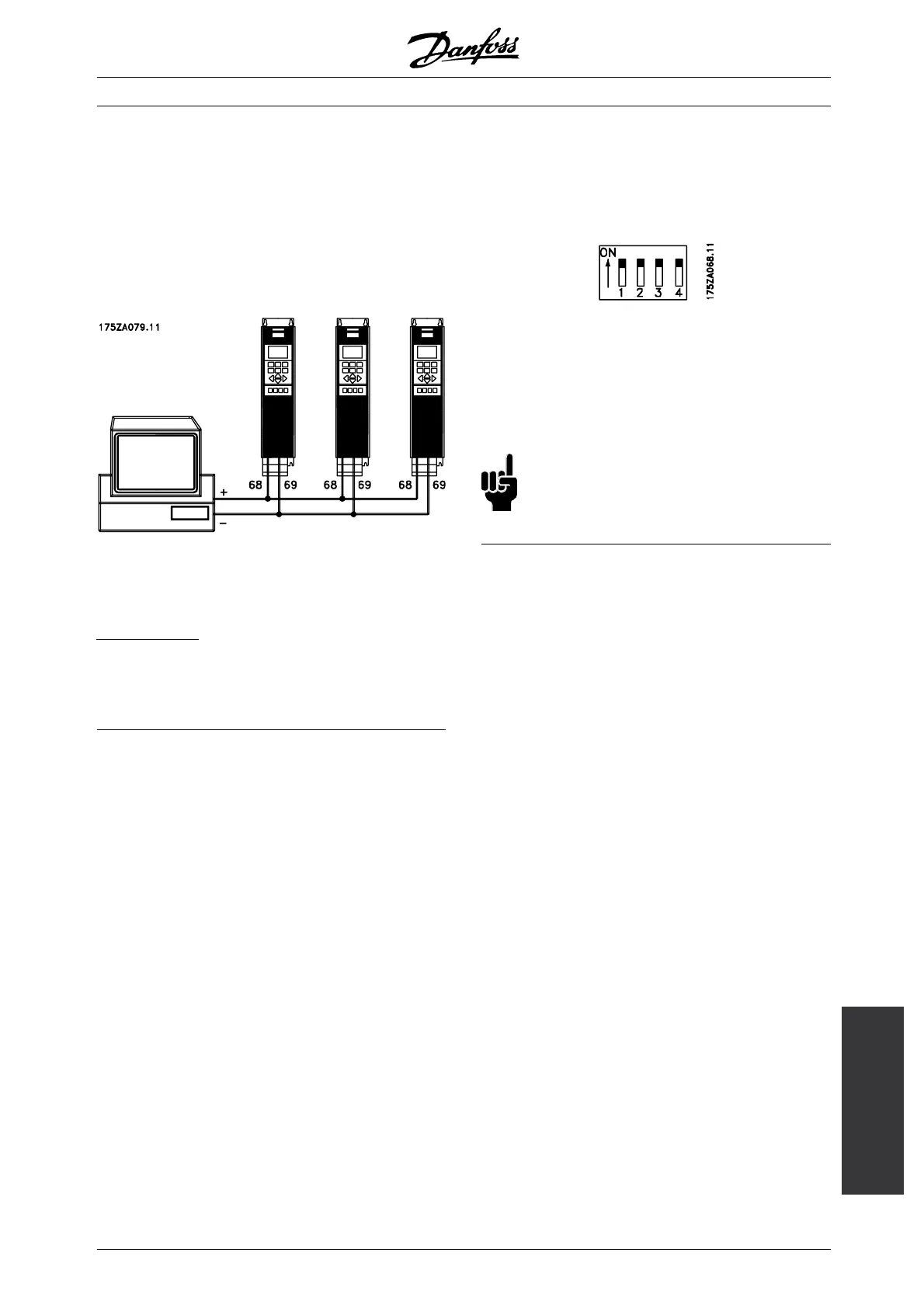
The serial bus connection in accordance with the RS
485 (2-conductor) norm is connected to terminals
68/69 of the frequency converter (signals P and N).
Signal P is the positive potential (TX+,RX+), while
signal N is the negative potential (TX-,RX-).
If more than one frequency converter is to be connected
to a given master, use parallel connections.
In order to avoid potential equalizing currents in the
screen, the cable screen can be earthed via terminal
61, which is connected to the frame via an RC-link.
B
us termination
The bus must be terminated by a resistor network
at both ends. For this purpose, set switches 2
and 3 on the control card for "ON".
■ DIP Switches 1-4
The dipswitch is located on the control card.
It is used for serial communication, terminals 68 and 69.
The switching position shown is the factory setting.
Switch 1 has no function.
Switches 2 and 3 are used for terminating an RS
485 interface, serial communication.
Switch 4 is used for separating the common potential
for the internal 24 V DC supply from the common
potential of the external 24 V DC supply.
NB!:
PleasenotethatwhenSwitch4isinposition
"OFF", the external 24 V DC supply is galvanically
isolated from the frequency converter.
MG.51.A9.02 - VLT is a registered Danfoss trademark
57
 Loading...


