VLT
®
5000 Series
Miscellaneous
■ Warnings
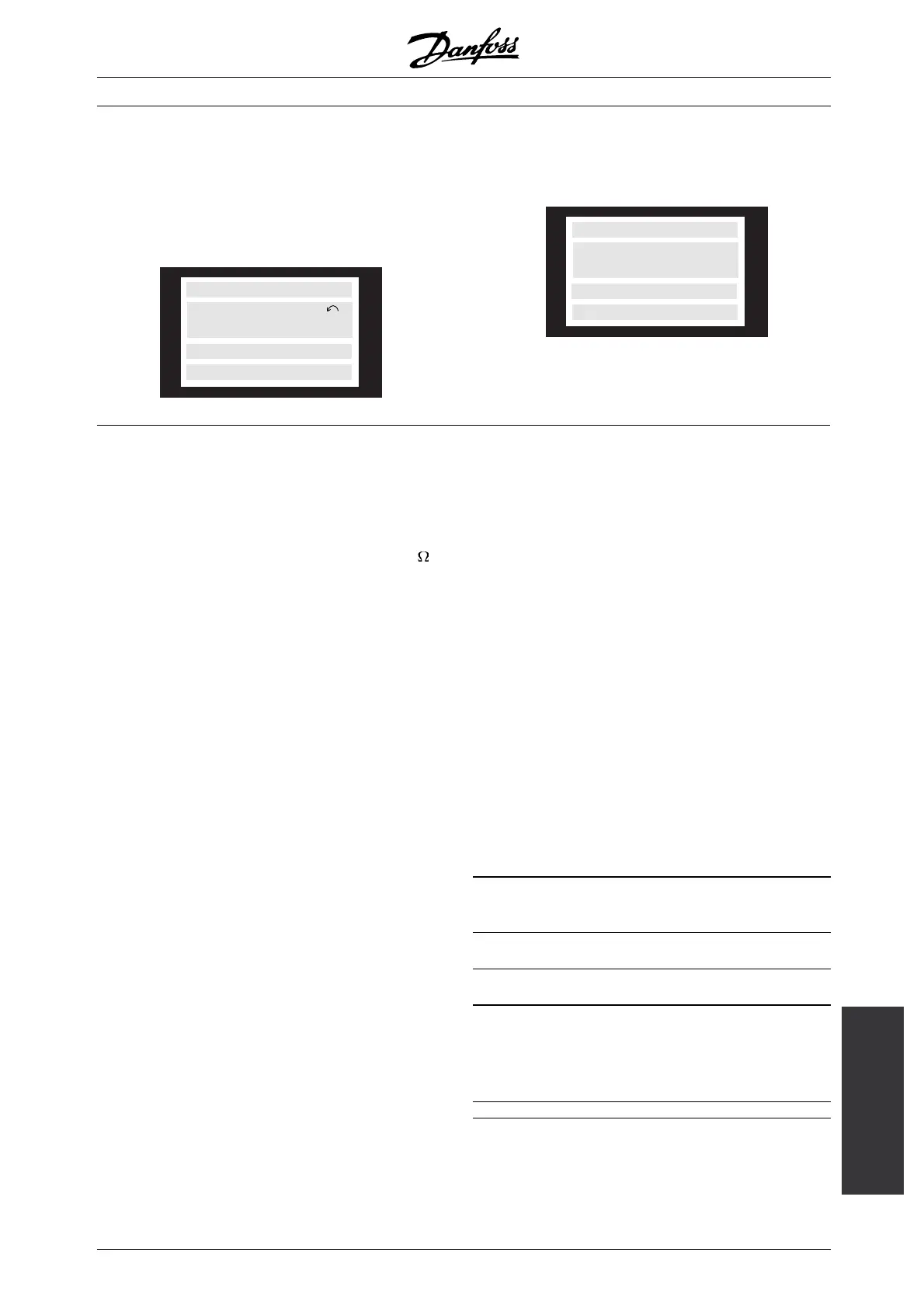
The display flashes between normal state and warning.
A warning comes up on the first and second line of
the display. See examples below. If parameter 027
is set to line 3/4, the warning will be shown in these
lines if the display is in read-out state 1-3.
SETUP
1
NO MOTOR
WARN. 3
Alarm messages
The alarm comes up in the 2. and 3. line of
the display, see example below:
ALARM:12
SETUP
1
TRIP (RESET)
TORQUE LIMIT
WARNING 1
Under 10 Volts (10 VOLT LOW):
The 10 Volts voltage from terminal 50 on the
control card is below 10 Volts.
Remove some of the load from terminal 50, as the 10
Volts supply is overloaded. Max. 17 mA/min. 590
.
WARNING/ALARM 2
Live zero fault (LIVE ZERO ERROR):
The current signal on terminal 60 is less than 50% of the
value set in parameter 315 Terminal 60,min. scaling.
WARNING/ALARM 3
No motor (NO MOTOR):
The motor check function (see parameter 122)
indicates that no motor has been connected to
the output of the frequency converter.
WARNING/ALARM 4
Phasefault(MAINSPHASELOSS):
A phase is missing on the supply side or the
mains voltage imbalance is too high.
This message can also appear if there is a fault in
the input rectifier on the frequency converter.
Check the supply voltage and supply currents
to the frequency converter.
WARNING 5
Voltage warning high
(DCLINKVOLTAGEHIGH):
The intermediate circuit voltage (DC) is higher than
the overvoltage limit of the control system. The
frequency converter is still active.
WARNING 6
Voltage warning low (DC LINK VOLTAGE LOW):
The intermediate circuit voltage (DC) is below the
undervoltage limit of the control system. The
frequency converter is still active.
WARNING/ALARM 7
Overvoltage (DC LINK OVERVOLT):
If the intermediate circuit voltage (DC) exceeds
the inverter overvoltage limit (see table), the
frequency converter will trip after the time set
in parameter 410 has passed.
Furthermore, the voltage will be stated in the display.
The fault can be eliminated by connecting a brake
resistor (if the frequency converter has an integral brake
chopper, EB or SB) or by extending the time chosen in
parameter 410. In addition, Brake function/overvoltage
control can be activated in parameter 400.
Alarm/warn-
ing limits:
VLT 5000
Series
3 x 200
-240V
3 x 380 -
500 V
3 x 525 -
600 V
3 X 525 -
690 v
[VDC] [VDC] [VDC] [VDC]
Undervolt-
age
211 402 557 553
Voltage
warning low
222 423 585 585
Voltage
warning
high (w/o
brake -
w/brake)
384/405 801/840
1)
943/965 1084/1109
Overvoltage 425 855 975 1130
The voltages stated are the intermediate circuit
voltage of the frequency converter with a tolerance
MG.51.A9.02 - VLT is a registered Danfoss trademark
169
 Loading...


