VLT
®
5000 Series
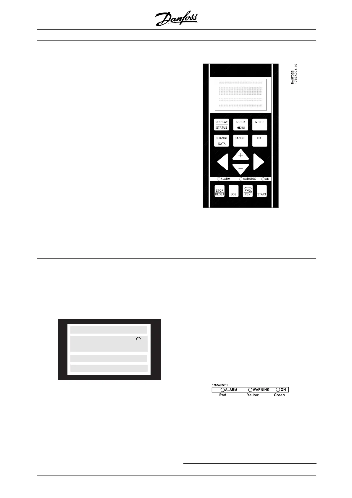
■ Control panel (LCP)
The front of the frequency converter features a
control panel - LCP (Local Control Panel), which
makes up a complete interface for operation and
monitoring of the VLT 5000 Series.
The control panel is detachable and can - as an
alternative - be installed up to 3 metres away from
the frequency converter, e.g. on a front panel,
by means of a mounting kit option.
The functions of the control panel can be
divided into three groups:
• display
• keys for changing program parameters
• keys for local operation
All data are indicated by means of a 4-line
alpha-numeric display, which in normal operation
is able to show 4 measurements and 3 operating
conditions continuously. During programming, all the
information required for quick, effective parameter
Setup of the frequency converter will be displayed. As
a supplement to the display, there are three LEDs for
voltage (power or 24 V external), warning and alarm.
All program parameters of the frequency converter can
be changed immediately from the control panel, unless
this function has been blocked via parameter 018.
■ Control panel - display
The LCD-display has rear lighting and a total of 4
alpha-numeric lines together with a box that shows
the direction of rotation (arrow) and the chosen
Setup as well as the Setup in which programming
is taking place if that is the case.
12345678
SETUP
1
12345678901234567890
12345678901234567890
12345678901234567890
175ZA443.10
1st line
2nd line
3rd line
4th line
1st line shows up to 3 measurements continuously
in normal operating status or a text which
explains the 2 nd line.
2nd line shows a measurement with related
unit continuously, regardless of status (except
in the case of alarm/warning).
3rd line is normally blank and is used in the menu
mode to show the selected parameter number or
parameter group number and name.
4th line is used in operating status for showing a
status text or in data change mode for showing the
mode or value of the selected parameter.
An arrow indicates the direction of rotation of the
motor. Furthermore, the Setup which has been
selected as the Active Setup in parameter 004 is
shown. When programming another Setup than
the Active Setup, the number of the Setup which
is being programmed will appear to the right. This
second Setup number will flash.
■ Control panel - LEDs
At the bottom of the control panel is a red alarm LED and
a yellow warning LED, as well as a green voltage LED.
If certain threshold values are exceeded, the alarm
and/or warning LED lights up together with a status
and alarm text on the contr
ol panel.
The voltage LED is activat
ed when the frequency
converter receives voltage, or 24 V external supply; at
the same time the rear lighting of the display will be on.
MG.51.A9.02 - VLT is a registered Danfoss trademark
66
 Loading...


