VLT
®
5000 Series
Function:
Reset to zero of kWh hour counter (parameter 602).
Description of choice:
If Reset [1] has been selected and when the [OK]
key is pressed, the kWh counter of the frequency
converter is reset. This parameter cannot be
selected via the serial port, RS 485.
NB!:
When the [OK] key has been activated, the
reset has been carried out.
619 Reset of hours-run counter
(RESET RUN. HOUR)
Value:
No reset (DO NOT RESET)
[0]
Reset (RESET COUNTER)
[1]
Function:
Reset to zero of hours-run counter (parameter 601).
Description of choice:
If Reset [1] has been selected and when the [OK] key
is pressed, the hours-run counter of the frequency
converter is reset. This parameter cannot be
selected via the serial port, RS 485.
NB!:
When the [OK] key has been activated, the
reset has been carried out.
620 Operating mode
(OPERATION MODE)
Value:
✭Normal function (NORMAL OPERATION)
[0]
Function with de-activated inverter
(OPER. W/INVERT.DISAB)
[1]
Control card test (CONTROL CARD TEST)
[2]
Initialisation (INITIALIZE)
[3]
Function:
In addition to its normal function, this parameter
can be used for two different tests.
Also, all parameters (except parameters
603-605) can be initialised.
NB!:
This function will not become active until the
mains supply to the frequency converter has
been turned off and then turned on again.
Description of choice:
Normal function [0] is selected for normal operation
with the motor in the selected application.
Function with deactivated inverter [1] is selected if
control is desired over the influence of the control
signal over the control card and its functions -
without the inverter driving the motor.
Control card test [2] is selected if control of
the analogue and digital inputs, as well as the
analogue, digital relay outputs and the +10 V control
voltage is desired. A test connector with internal
connections is required for this test.
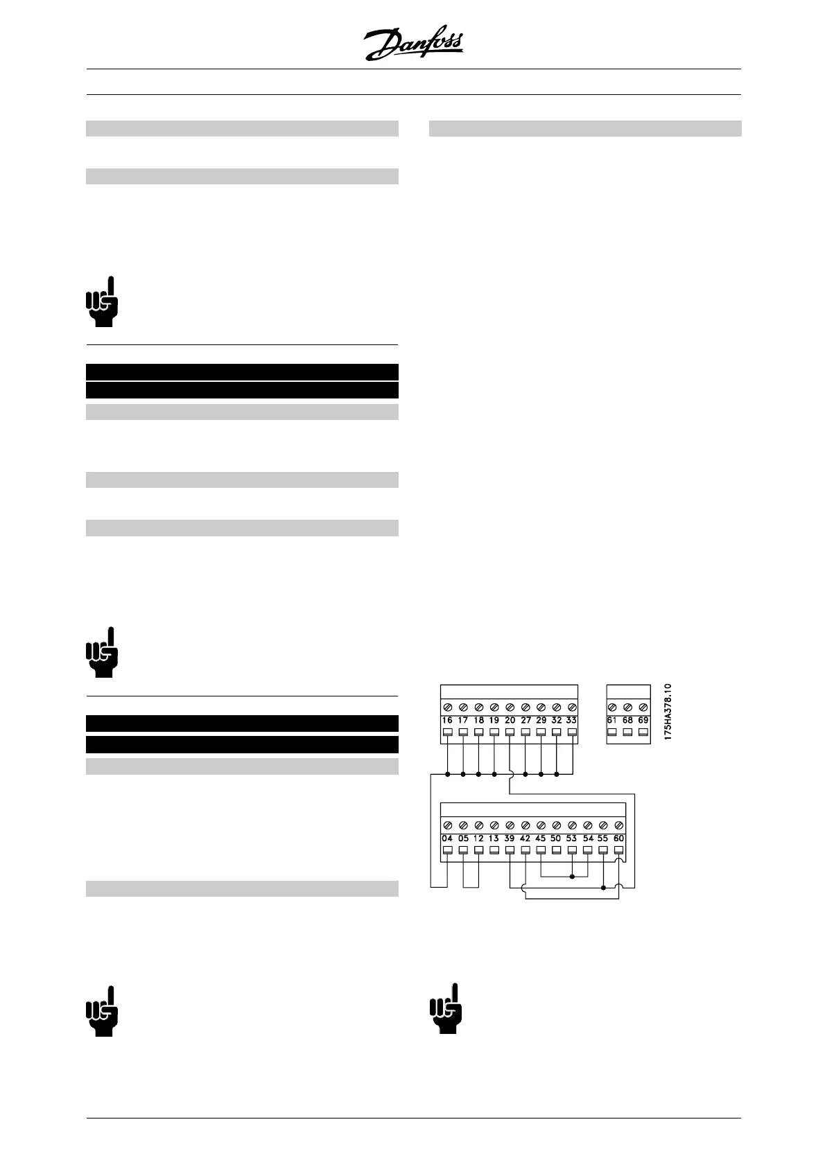
Use the following procedure for the control card test:
1. Select Control card test.
2. Cut off the mains supply and wait for the
light in the display to go out.
3. Insert the test plug (see below).
4. Connect to mains.
5. The frequency converter expects the [OK] key to be
pressed (if no LCP, set to Normal operation,when
the frequency converter will start up as usual).
6. Carry out various tests.
7. Press the [OK] key.
8. Parameter 620 is automatically set to
Normal operation.
If a test fails, the frequency converter will move into
an infinite loop. Replace control card.
Test plugs:
Inialisation [3] is selected if the factory setting of
the unit is desired without resetting parameters
500, 501 + 600 - 605 + 615 - 617.
NB!:
The motor must be stopped before initialisation
can be carried out.
✭
= factory setting. () = display text [] = value for use in communication via serial communication port
MG.51.A9.02 - VLT is a registered Danfoss trademark
160
 Loading...


