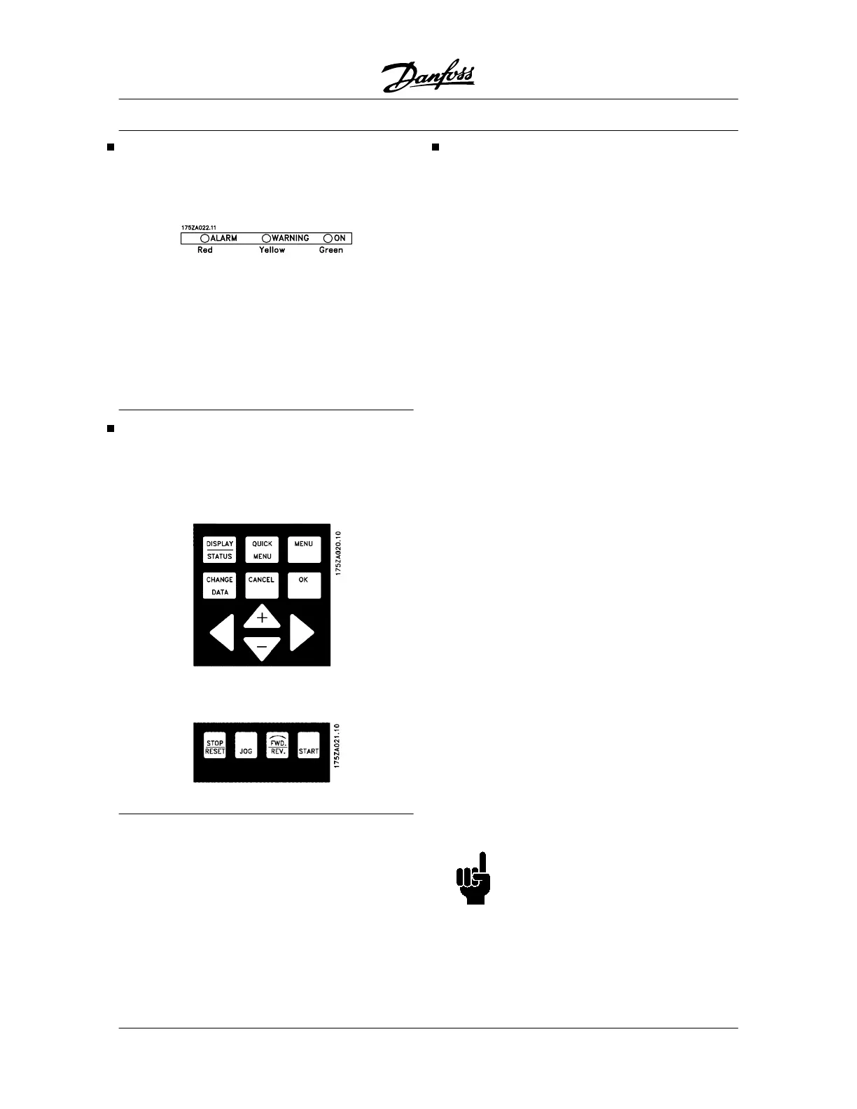
Control panel - LEDs
At the bottom of the control panel is a red alarm LED
and a yellow warning LED, as well as a green voltage
LED.
If certain threshold values are exceeded, the alarm
and/or warning LED lights up together with a status
and alarm text on the control panel.
The voltage LED is activated when the adjustable fre-
quency drive receives voltage, or 24 V external supply;
at the same time the rear lighting of the display will be
on.
Control panel - control keys
The control keys are divided into functions. This
means that the keys between display and indicator
lamps are used for parameter Setup, including choice
of display indication during normal operation.
Keys for local control are found under the indicator
LEDs.
Control key functions
[DISPLAY / STATUS] is used for selecting the mode
of display or for changing back to Display mode from
either the Quick menu mode or the Menu mode.
[QUICK MENU] is used for programming the param-
eters that belong under the Quick menu mode. It is
possible to switch directly between Quick menu mode
and Menu mode.
[MENU] is used for programming all parameters. It is
possible to switch directly between Menu mode and
Quick menu mode.
[CHANGE DATA ] is used for changing the param-
eter selected either in the Menu mode or the Quick
menu mode.
[CANCEL] is used if a change of the selected pa-
rameter is not to be carried out.
[OK] is used for confirming a change of the parameter
selected.
[+/-] is used for selecting parameter and for changing
the chosen parameter or for changing the read out in
line 2.
[<>] is used for selecting group and to move the cur-
sor when changing numerical parameters.
[STOP / RESET] is used for stopping the motor con-
nected or for resetting the adjustable frequency drive
after a drop-out (trip). Can be selected via parameter
014 to be active or inactive. If stop is activated, line 2
will flash, and [START] must be activated.
[JOG] overrides the output frequency to a preset fre-
quency while the key is kept down. Can be selected
via parameter 015 to be active or inactive.
[FWD / REV] changes the direction of rotation of the
motor, which is indicated by means of the arrow on
the display although only in Local. Can be selected
via parameter 016 to be active or inactive.
[START] is used for starting the adjustable frequency
drive after stop via the "Stop" key. Is always active,
but cannot override a stop command given via the
terminal strip.
NOTE
If the keys for local control have been se-
lected as active, they will remain active
both when the frequency has been set for
Local Control and for Remote Control via
parameter 002, although with the excep-
VLT
®
5000 Series
72 MG.51.C5.22 - VLT
p
is a registered Danfoss trademark.
 Loading...

