tion of [Fwd/rev], which is only active in
Local operation.
NOTE
If no external stop function has been se-
lected and the [Stop] key has been selec-
ted as inactive, the motor can be started
and can only be stopped by disconnecting
the voltage to the motor.
Control panel - display read-outs
The display read-out state can be varied - see the list
below - depending on whether the adjustable frequen-
cy drive is in normal operation or is being programmed.
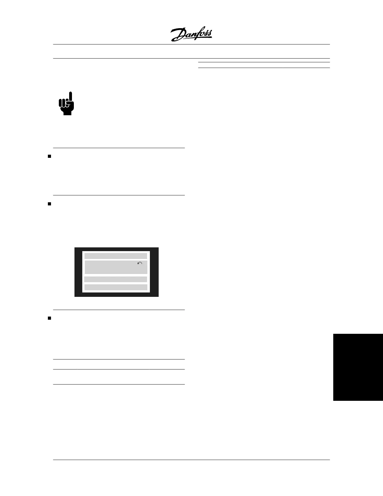
Display mode
In normal operation, up to 4 different operating varia-
bles can be indicated continuously: 1.1 and 1.2 and
1.3 and 2, and in line 4 the present operating status or
alarms and warnings that have arisen.
195NA113.10
VAR 2
SETUP
1
STATUS
VAR 1.1 VAR 1.2 VAR 1.3
Display mode - selection of read-outstate
There are three options in connection with the choice
of read-out state in the Display mode - I, II and III. The
choice of read-out state determines the number of op-
erating variables read out.
Read-out
state:
I: II: III:
Line 1 Description for op-
erating variable in
line 2
Data value for 3
operating varia-
bles in line 1
Description for 3
operating varia-
bles in line 1
The table below gives the units linked to the variables
in the first and second line of the display.
Operating variable: Unit:
Reference [%]
Reference [unit]
Feedback [unit]
Frequency [Hz]
Frequency x scaling [-]
Motor current [A]
Torque [%]
Power [kW]
Power [HP]
Output energy [kWh]
Motor voltage [V]
DC-link voltage [V]
Motor thermal load [%]
VLT thermal load [%]
Hours run [Hours]
Input status, dig. Input [Binary code]
Input status, analog terminal 53 [V]
Input status, analog terminal 54 [V]
Input status, analog terminal 60 [mA]
Pulse reference [Hz]
External reference [%]
Status word [Hex]
Brake effect/2 min. [kW]
Brake effect/sec. [kW]
Heat sink temp. [ºC]
Alarm word [Hex]
Control word [Hex]
Warning word 1 [Hex]
Extended status word [Hex]
Communication option card warning [Hex]
RPM
[min
-1
]
RPM x scaling [ - ]
LCP Display text [ - ]
Operating variables 1.1 and 1.2 and 1.3 in the first line,
and operating variable 2 in the second line are selec-
ted via parameter 009, 010, 011 and 012.
VLT
®
5000 Series
MG.51.C5.22 - VLT
p
is a registered Danfoss trademark. 73
Operation of the VLT
 Loading...

