4.3 Mechanical Installation
Preparation of the mechanical installation of the adjustable frequency drive must be done carefully to ensure proper results and to avoid additional work
during installation. Start by taking a close look at the mechanical drawings at the end of this instruction manual to become familiar with the space demands.
4.3.1 Tools Needed
To perform the mechanical installation, the following tools are needed:
• Drill with 0.39 or 0.47 in [10 or 12 mm] drill.
• Tape measure
• Wrench with relevant metric sockets (7–17 mm)
• Extensions to wrench
• Sheet metal punch for conduits or cable connectors in IP 21/Nema 1 and IP 54 units
• Lifting bar to lift the unit (rod or tube max. Ø25 mm (1 inch), able to lift a minimum of 2204 lbs [1000 kg]).
• Crane or other lifting aid to place the adjustable frequency drive in position
• A Torx T50 tool is needed to install the E1 in IP21 and IP54 enclosure types.
4.3.2 General Considerations
Space
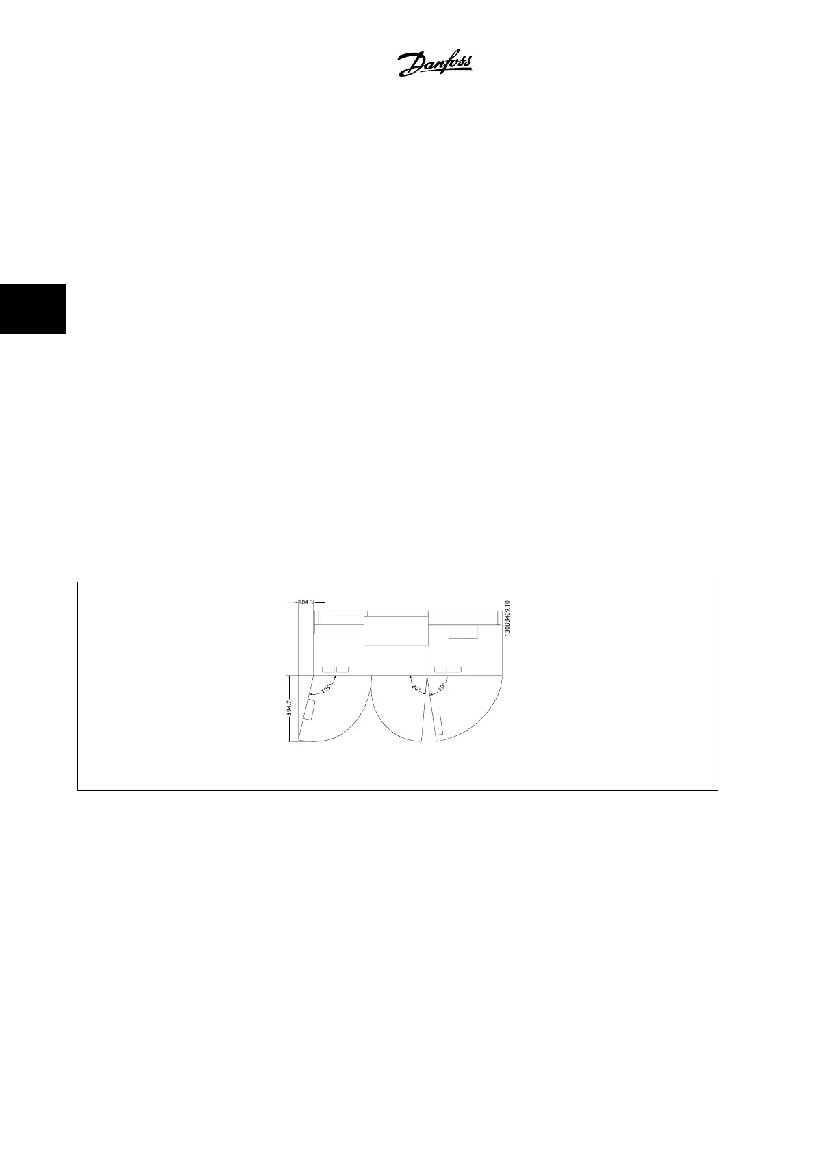
Ensure proper space above and below the adjustable frequency drive to allow airflow and cable access. In addition, space in front of the unit must be
considered to allow the panel door to be opened.
Figure 4.9: Space in front of IP21/IP54 enclosure type, frame size D11.
4 How to Install
VLT AQUA Low Harmonic Drive Instruction
Manual
4-12
MG.20.T1.22 - VLT
®
is a registered Danfoss trademark
4
 Loading...


