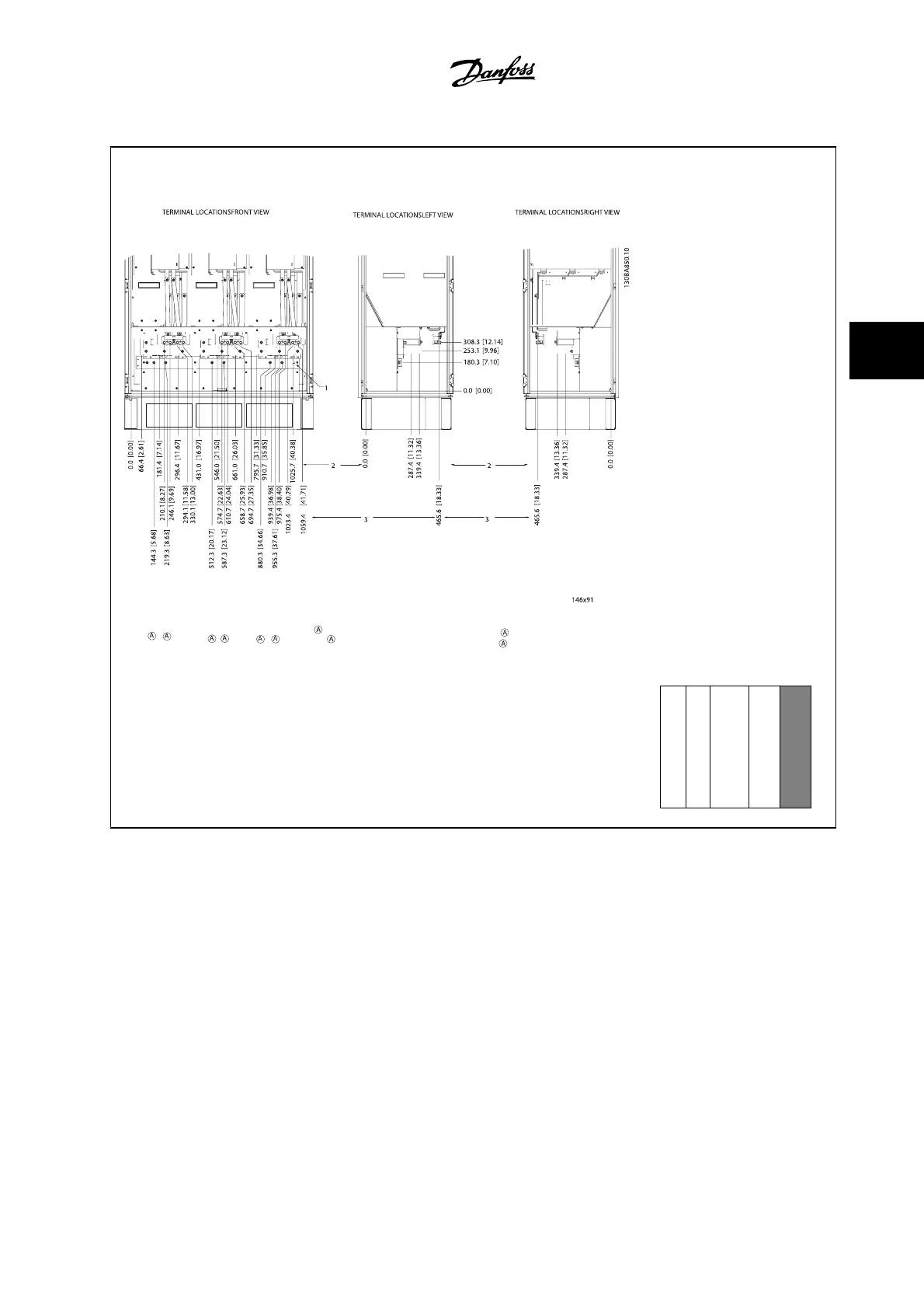
Terminal locations - Inverter
Figure 4.19: Terminal locations - Inverter Cabinet (front, left and right side view). The connector plate is
1.65 in [42 mm] below .0 level.
1) Ground bar
2) Motor terminals
3) Brake terminals
Section shown
↓
4.3.8 Cooling and Airflow
Cooling
Cooling can be obtained in different ways, by using the cooling ducts in the bottom and the top of the unit, by taking air in and out the back of the unit
or by combining the cooling possibilities.
Back cooling
The backchannel air can also be ventilated in and out the back of a Rittal TS8 enclosure. This offers a solution where the backchannel could take air from
outside the facility and return the heat losses outside the facility thus reducing air-conditioning requirements.
VLT AQUA Low Harmonic Drive Instruction
Manual
4 How to Install
MG.20.T1.22 - VLT
®
is a registered Danfoss trademark
4-23
4
 Loading...


