Installation requirements:
The overall electrical safety of the adjustable frequency drive requires special installation considerations regarding:
• Fuses and circuit breakers for overcurrent and short-circuit protection
• Selection of power cables (line power, motor, brake, load sharing and relay)
• Grid configuration (IT,TN, grounded leg, etc.)
• Safety of low-voltage ports (PELV conditions).
Consult the relevant clauses in these instructions and in the Design Guide for information about the installation requirements.
2.1.5 Avoid unintended start
While the adjustable frequency drive is connected to line power, the motor can be started/stopped using digital commands, bus com-
mands, references or via the Local Control Panel.
• Disconnect the adjustable frequency drive from line power whenever personal safety considerations make it necessary to
avoid an unintended start.
• To avoid unintended start, always activate the [OFF] key before changing parameters.
• Unless terminal 37 is turned off, an electronic fault, temporary overload, a fault in the line power supply, or lost motor
connection may cause a stopped motor to start.
2.1.6 Safe Stop Installation
To carry out an installation of a Category 0 Stop (EN60204) in
conformity with Safety Category 3 (EN954-1), follow these in-
structions:
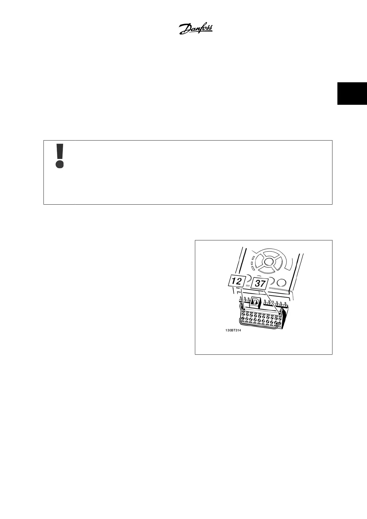
1. The bridge (jumper) between Terminal 37 and 24 V DC must be
removed. Cutting or breaking the jumper is not sufficient. Re-
move it entirely to avoid short-circuiting. See jumper in figure.
2. Connect terminal 37 to 24 V DC by a short circuit-protected ca-
ble. The 24 V DC voltage supply must be interruptible by an
EN954-1 category 3 circuit interrupt device. If the interrupt de-
vice and the adjustable frequency drive are placed in the same
installation panel, you can use a non-shielded cable instead of
a shielded one.
Figure 2.1: Bridge jumper between terminal 37 and 24 VDC
The figure below shows a Stopping Category 0 (EN 60204-1) with safety Category 3 (EN 954-1). The circuit interruption is caused by an opening door
contact. The figure also shows how to connect a non-safety-related hardware coast.
VLT AQUA Low Harmonic Drive Instruction
Manual
2 Safety
MG.20.T1.22 - VLT
®
is a registered Danfoss trademark
2-3
2
 Loading...


