130BB438.10
Remove this inductor module
6. After the inductor module is removed, the filter and drive sections can be attached to one another. Four corner brackets and six side brackets
will be required for this operation. They will be included in a bag with the appropriate screws. After the internal brackets are installed, the two
top “L” shaped brackets will be installed to act as load points for moving the complete assembly.
7. Once all the brackets have been installed, the inductor module can be reassembled to its previous location.
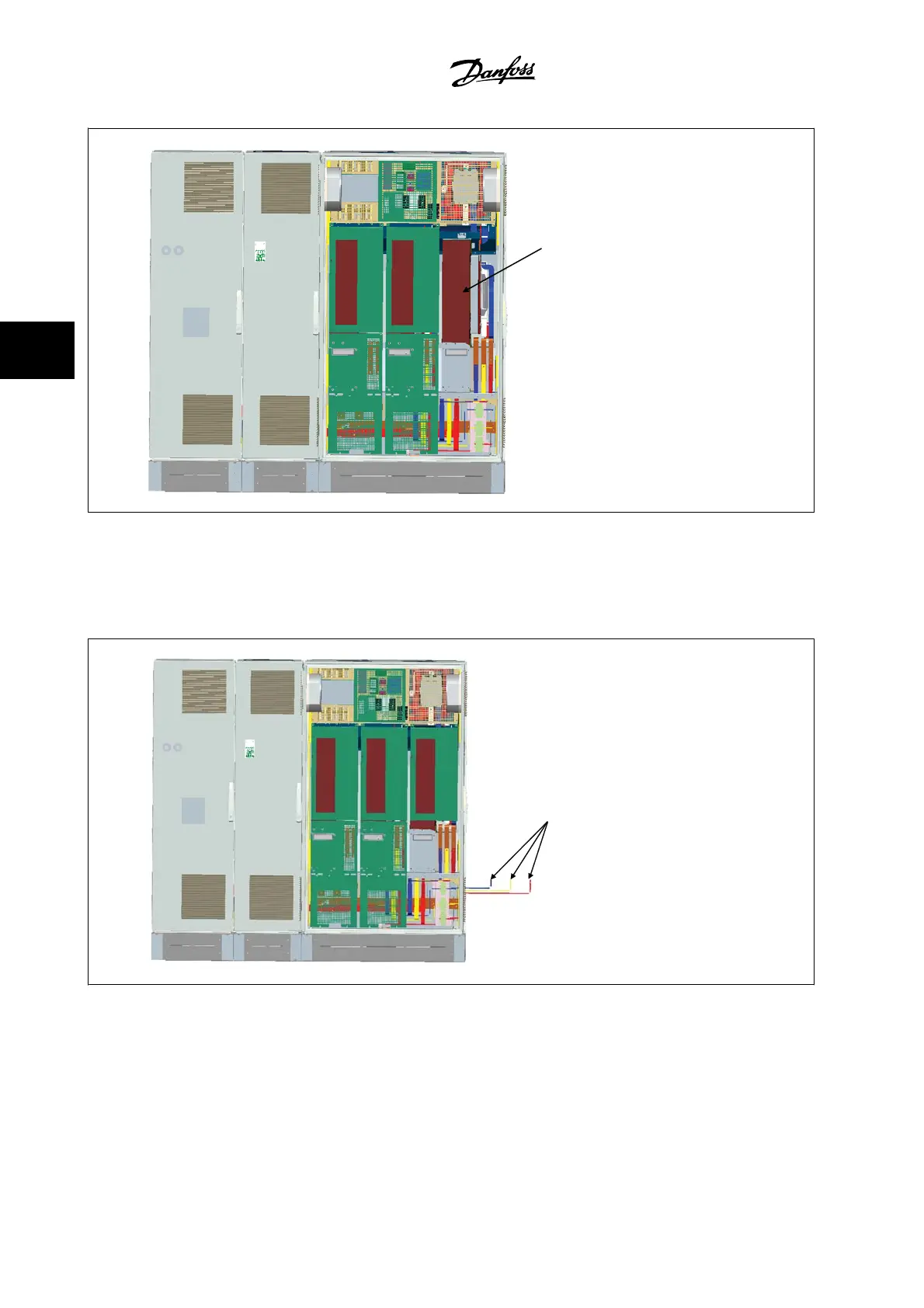
8. Now the three line power bus bars, included in as a kit with the drive, can be attached from the filter section to the rectifier section.
130BB439.10
Bus bars connecting to rectifier section of the drive
9. Once the line power bus bars are connected, the lower covers on both the LCL and rectifier sections can be reinstalled.
10. A control wire connection will need to be made between the filter section and the drive section. It will consist of two connectors which will plug
into one another near the upper shelf of the LCL cabinet. See description below.
11. The doors can now be closed and locked. The drive is ready for operation.
4 How to Install
VLT AQUA Low Harmonic Drive Instruction
Manual
4-16
MG.20.T1.22 - VLT
®
is a registered Danfoss trademark
4
 Loading...


