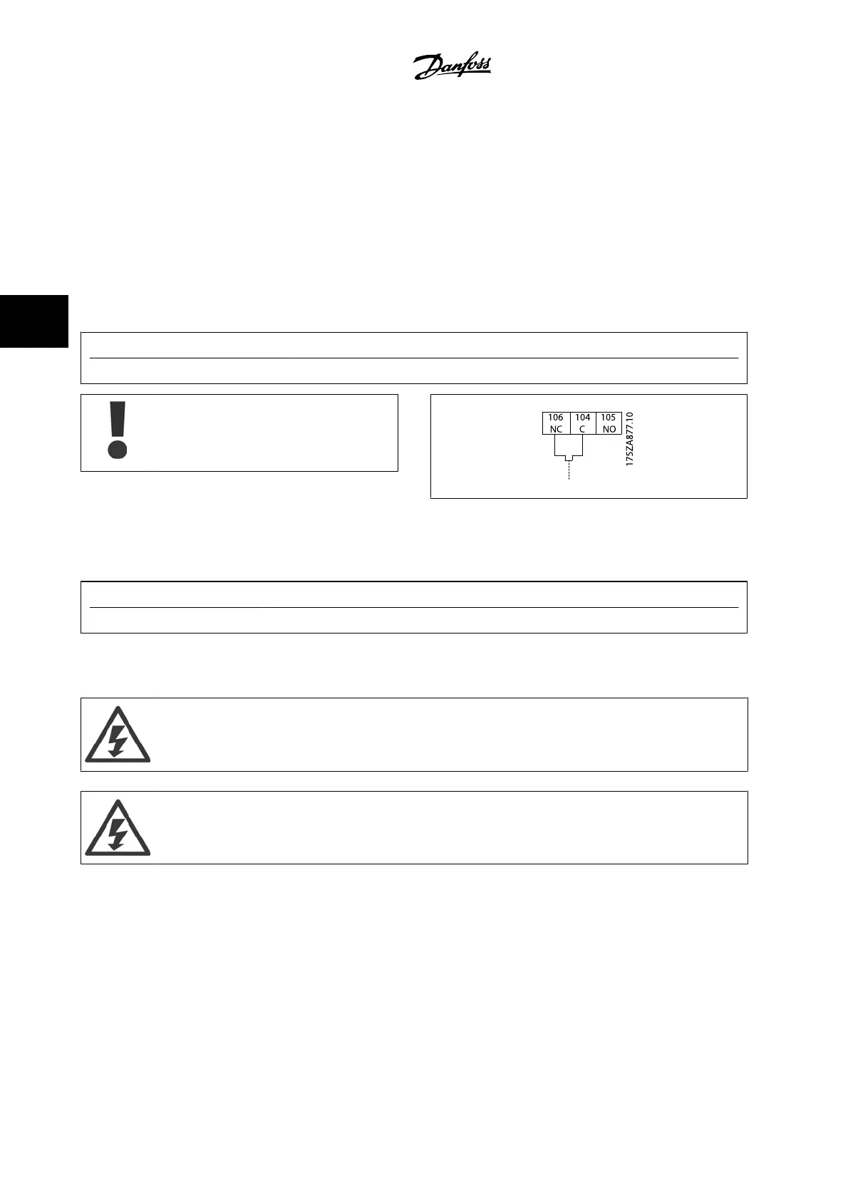
4.6.9 Brake Resistor Temperature Switch
Frame size D-E-F
Torque: 0.5-0.6 Nm (5 in-lbs)
Screw size: M3
This input can be used to monitor the temperature of an externally connected brake resistor. If the connection between 104 and 106 is removed, the
adjustable frequency drive will trip on warning/alarm 27, “Brake IGBT”.
A KLIXON switch must be installed that is `normally closed' in series with the existing connection on either 106 or 104. Any connection to this terminal
must be double insulated to high voltage to maintain PELV.
Normally closed: 104-106 (factory installed jumper).
Terminal No. Function
106, 104, 105 Brake resistor temperature switch.
If the temperature of the brake resistor gets too high
and the thermal switch drops out, the adjustable fre-
quency drive will stop braking. The motor will start
coasting.
4.6.10 Load Sharing
Terminal No. Function
88, 89 Load sharing
The connection cable must be shielded and the max. length from the adjustable frequency drive to the DC bar is limited to 82 ft [25 m].
Load sharing enables the linking of the DC intermediate circuits of several adjustable frequency drives.
Please note that voltages up to 1099 V DC may occur on the terminals.
Load sharing calls for extra equipment and safety considerations. For further information, see load sharing Instructions MI.50.NX.YY.
Please note that a line power disconnect may not isolate the adjustable frequency drive due to DC link connection
4 How to Install
VLT AQUA Low Harmonic Drive Instruction
Manual
4-46
MG.20.T1.22 - VLT
®
is a registered Danfoss trademark
4
 Loading...


