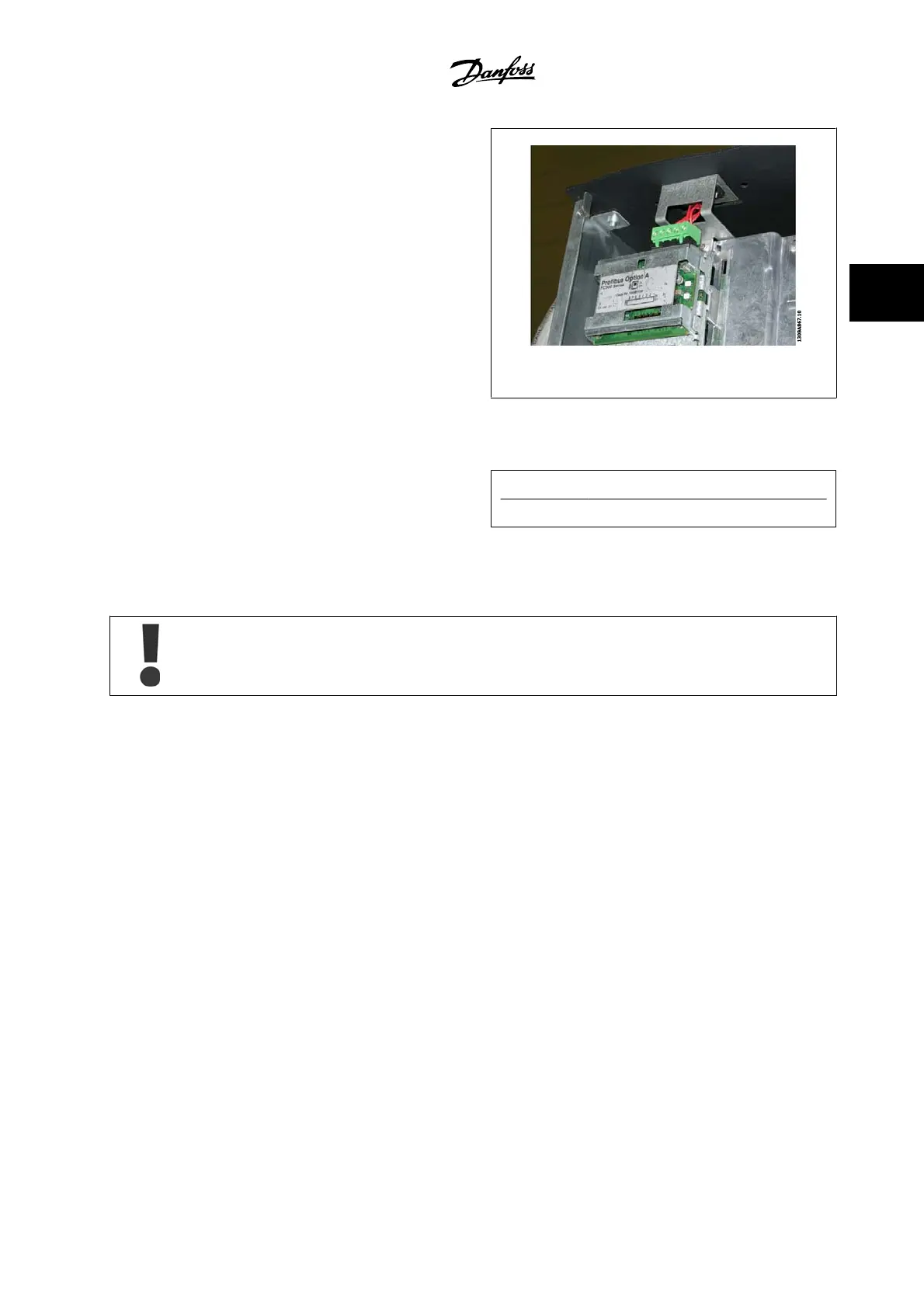
In the Chassis (IP00) and NEMA 1 units, it is also possible to connect the
serial communication bus from the top of the unit as shown on the picture
to the right. On the NEMA 1 unit, a cover plate must be removed.
Kit number for serial communication bus top connection: 176F1742
Figure 3.52: Top connection for serial communication bus.
Installation of 24 Volt external DC Supply
Torque: 0.5–0.6 Nm (5 in-lbs)
Screw size: M3
No.
Function
35 (-), 36 (+) 24 V external DC supply
24 VDC external supply can be used as low voltage supply to the control card and any option cards installed. This enables full operation of the LCP
(including parameter setting) without a connection to line power. Please note that a warning of low voltage will be given when 24 V DC has been connected;
however, there will be no tripping.
Use 24 V DC supply of type PELV to ensure correct galvanic isolation (type PELV) on the control terminals of the adjustable frequency
drive.
3.6.21 Access to Control Terminals
All terminals to the control cables are located beneath the LCP. They are accessed by opening the door of the IP21/ 54 version or removing the covers
of the IP00 version.
VLT AQUA High Power Instruction Manual 3 How to Install
MG.20.P3.22 - VLT
®
is a registered Danfoss trademark
3-65
3
 Loading...


