4.2.1 EMC Interference
1
2
2
3
3
4
5
3
2
5
6
3
7
8
6
8
9
7
9
10
130BC644.10
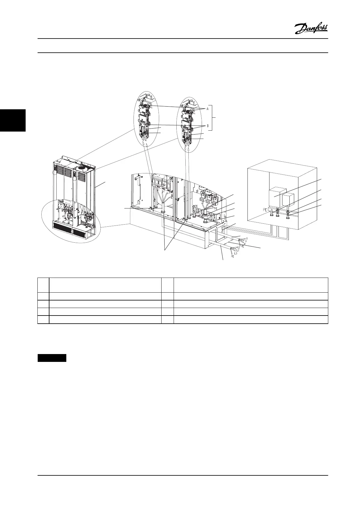
1 Customer control termination points–options A and
B
6 Motor output cable, 3-phase and PE (not screened)
2 Screened control wiring 7 Cable gland
3 Cable clamp 8 Clearance, minimum 200 mm
4 Customer control input 9 Mains input cable, 3-phase and reinforce PE (not screened)
5
Potential equialisation wire [minimum 16 mm
2
]
10 Low harmonic drive (LHD)
Figure 4.1 EMC-correct Installation
NOTICE!
EMC Interference
Use screened cables for motor and control wiring. Separate the LHD mains input cable, motor cable, and control wiring.
Minimum 200 mm (7.9 in) clearance between power, motor, and control cables is required. Maximise this clearance to
minimise EMC emissions. This reduces the risk of interference between the LHD and other electronic devices.
Electrical Installation
VLT
®
AutomationDrive FC 302 Low Harmonic Drive
132–630 kW
36 Danfoss A/S © Rev. 04/2015 All rights reserved. MG37A322
44
 Loading...


