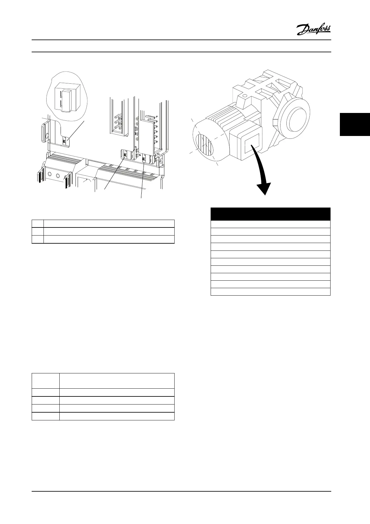
1 Bus termination switch
2 A54 switch
3 A53 switch
Figure 4.18 Bus Termination Switch, A53, and A54 Switch
Locations
4.10
Final Set-up and Test
Before operating the frequency converter, perform a nal
test of the installation:
1. Locate the motor name plate to nd out whether
the motor is star- (Y) or delta- connected (Δ).
2. Enter the motor name plate data in the
parameter list. Access the list by pressing the
[Quick Menu] key and selecting Q2 Quick Set-up.
See Table 4.11.
1. Parameter 1-20 Motor Power [kW]
Parameter 1-21 Motor Power [HP]
2. Parameter 1-22 Motor Voltage
3. Parameter 1-23 Motor Frequency
4. Parameter 1-24 Motor Current
5. Parameter 1-25 Motor Nominal Speed
Table 4.11 Quick Set-up Parameters
3~ MOTOR NR. 1827421 2003
S/E005A9
1,5 KW
n 31,5 /MIN. 400 Y V
n 1400 /MIN. 50 Hz
cos 0,80 3,6 A
1,7L
B IP 65 H1/1A
130BT307.10
BAUER D-7 3734 ESLINGEN
Figure 4.19 Motor Name Plate
3. Perform an automatic motor adaptation (AMA) to
ensure optimum performance.
3a Connect terminal 27 to terminal 12 or
set parameter 5-12 Terminal 27 Digital
Input to [0] No operation.
3b Activate the AMA in
parameter 1-29 Automatic Motor
Adaptation (AMA).
3c Select either complete or reduced AMA.
If an LC lter is mounted, run only the
reduced AMA, or remove the LC lter
during the AMA procedure.
3d Press [OK]. The display shows Press
[Hand On] to start.
3e Press [Hand On]. A progress bar
indicates whether the AMA is in
progress.
Electrical Installation Installation Manual
MG37A322 Danfoss A/S © Rev. 04/2015 All rights reserved. 49
4 4
 Loading...


