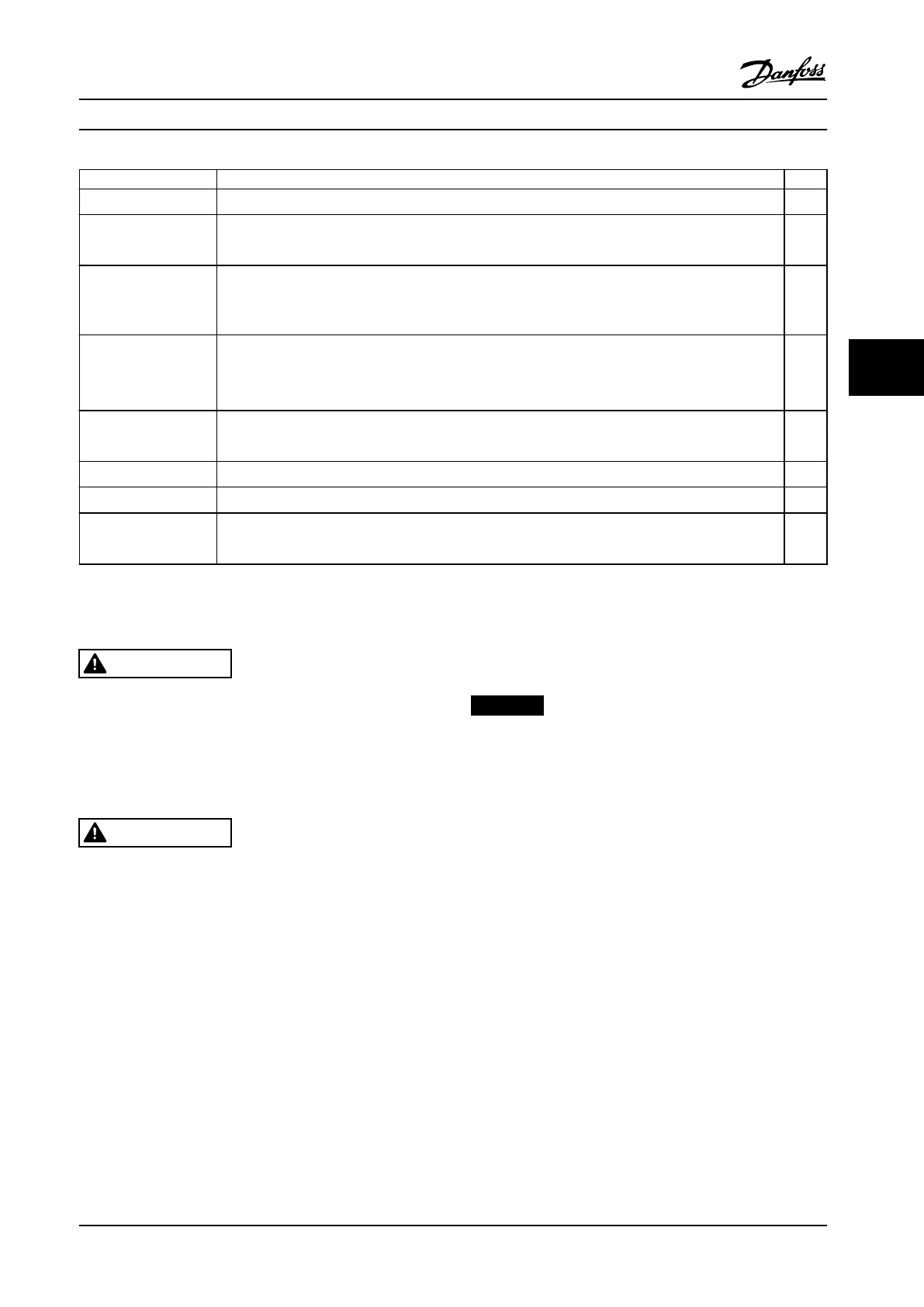
Inspect for Description
☑
EMC considerations
•
Check for proper installation regarding electromagnetic compatibility.
Environmental consider-
ations
•
See equipment label for the maximum ambient operating temperature limits.
•
Humidity levels must be 5–95% non-condensing
Fusing and circuit
breakers
•
Check for proper fusing or circuit breakers.
•
Check that all fuses are inserted rmly and in operational condition and that all circuit breakers are
in the open position.
Grounding
•
The unit requires a ground wire from its chassis to the building ground.
•
Check for good ground connections that are tight and free of oxidation.
•
Grounding to conduit or mounting the back panel to a metal surface is not a suitable ground.
Input and output power
wiring
•
Check for loose connections.
•
Check that motor and line power are in separate conduits or separated shielded cables.
Panel interior
•
Make sure that the unit interior is free of debris and corrosion
Switches
•
Ensure that all switch and disconnect settings are in the proper positions.
Vibration
•
Check that the unit is mounted solidly or that shock mounts are used, as necessary.
•
Check for an unusual amount of vibration.
Table 5.1 Start-up Checklist
5.2
Applying Power to the Equipment
WARNING
HIGH VOLTAGE!
Adjustable frequency drives contain high voltage when
connected to AC line power. Installation, start-up and
maintenance should be performed by qualied
personnel only. Failure to comply could result in death or
serious injury.
WARNING
UNINTENDED START!
When the adjustable frequency drive is connected to AC
line power, the motor may start at any time. The
adjustable frequency drive, motor, and any driven
equipment must be in operational readiness. Failure to
comply could result in death, serious injury, equipment,
or property damage.
1. Conrm that the input voltage is balanced within
3%. If not, correct input voltage imbalance before
proceeding.
2. Ensure that optional equipment wiring (if present)
matches the installation application.
3. Ensure that all operator devices are o. Panel
doors should be closed or cover mounted.
4. Apply power to the unit. Do not start the
adjustable frequency drive at this time. For units
with a disconnect switch, turn the switch on to
apply power.
NOTICE!
If the status line at the bottom of the LCP reads AUTO
REMOTE COASTING or Alarm 60 External Interlock is
displayed, this indicates that the unit is ready to operate
but is missing an input signal on terminal 27.
5.3 Local Control Panel Operation
5.3.1 Local Control Panel
The local control panel (LCP) is the combined display and
keypad on the front of the unit. The low harmonic drive
includes 2 LCPs: 1 to control the frequency converter side
and 1 to control the lter side.
The LCP has several functions:
•
Control speed of frequency converter when in
local mode.
•
Start and stop in local mode.
•
Display operational data, status, warnings, and
alarms.
•
Programme frequency converter and active lter
functions.
Start-up and Functional Tes... Installation Manual
MG37A322 Danfoss A/S © Rev. 04/2015 All rights reserved. 53
5 5
 Loading...


