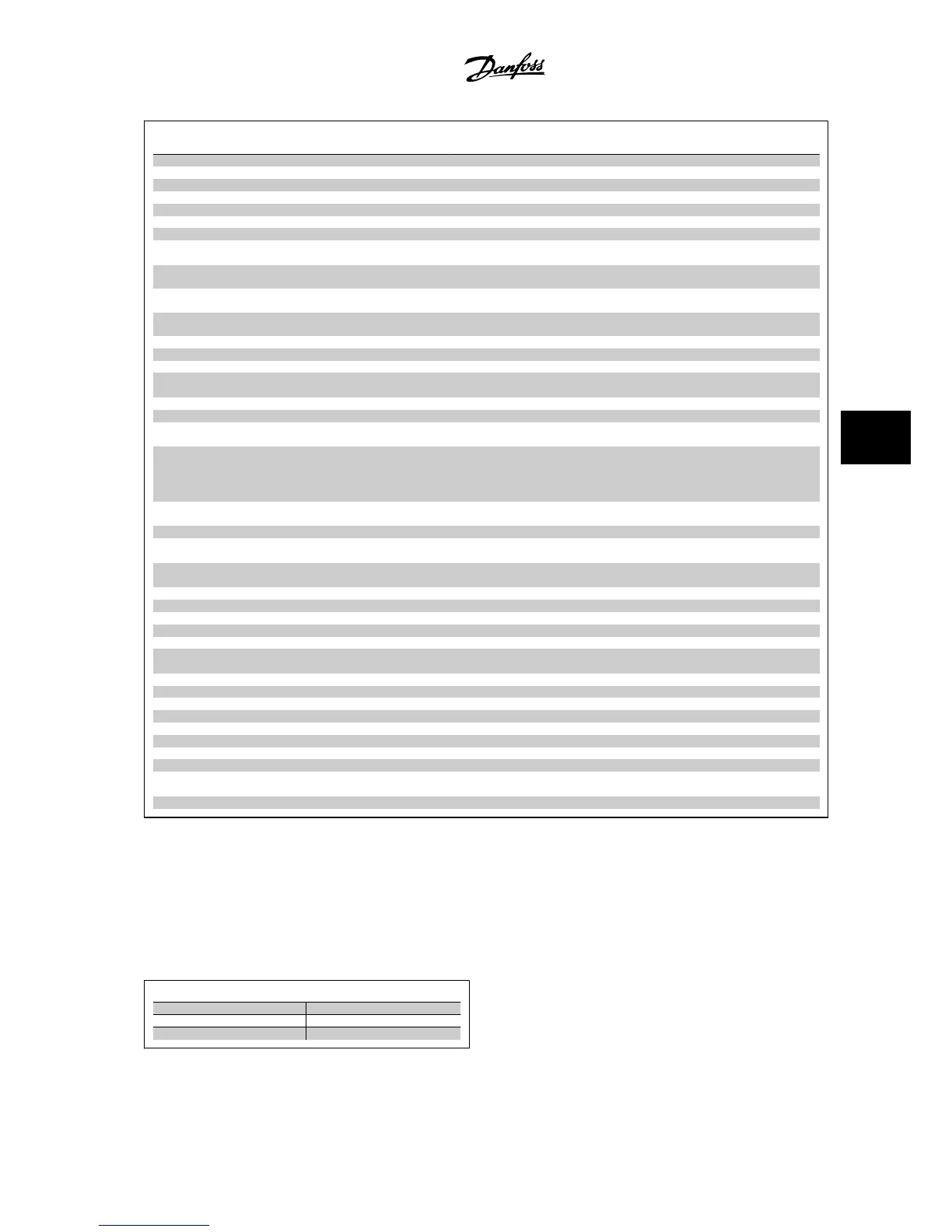
No. Description Warning Alarm/Trip Alarm/Trip Lock Parameter
Reference
54 AMA motor too small X
55 AMA parameter out of range X
56 AMA interrupted by user X
57 AMA timeout X
58 AMA internal fault X X
59 Current limit X
60 External Interlock X X
61 Feedback Error (X) (X) Par. 4-30
Motor Feed-
back Loss Function
62 Output Frequency at Maximum Limit X
63 Mechanical Brake Low (X) Par. 2-20
Release Brake
Current
64 Voltage Limit X
65 Control Board Over-temperature X X X
66 Heatsink Temperature Low X
67 Option Configuration has Changed X
68 Safe Stop (X)
(X)
1)
Par. 5-19
Terminal 37
Safe Stop
69 Pwr. Card Temp X X
70 Illegal FC configuration X
71 PTC 1 Safe Stop X
X
1)
Par. 5-19
Terminal 37
Safe Stop
72 Dangerous Failure
X
1)
Par. 5-19
Terminal 37
Safe Stop
73 Safe Stop Aut Re (X) (X) Par. 5-19
Terminal 37
Safe Stop
76 Pwr Unit Setup X
77 Reduced power mode X Par. 14-59
Actual Num-
ber of Inverter Units
78 Tracking Error (X) (X) Par. 4-34
Tracking Error
Function
79 Illegal PS config X X
80 Drive Initialized to Default Value X
81 CSIV corrupt X
82 CSIV param err X
85 Profibus/Profisafe Error X
90 Feedback Monitor (X) (X) Par. 17-61
Feedback
Signal Monitoring
91 Analog input 54 wrong settings X S202
100-199 See Instruction Manual for MCO 305
243 Brake IGBT X X
244 Heatsink temp X X X
245 Heatsink sensor X X
246 Pwr.card supply X X
247 Pwr.card temp X X
248 Illegal PS config X X
250 New spare part X Par. 14-23
Typecode
Setting
251 New Type Code X X
Table 6.2: Alarm/Warning code list
(X) Dependent on parameter
1) Cannot be auto reset via par. 14-20
Reset Mode
A trip is the action when an alarm has appeared. The trip will coast the motor and can be reset by pressing the reset button or make a reset by a digital
input (par. group 5-1* [1]). The original event that caused an alarm cannot damage the adjustable frequency drive or cause dangerous conditions. A trip
lock is an action that occurs in conjunction with an alarm, which may cause damage to the adjustable frequency drive or connected parts. A trip lock
situation can only be reset by power cycling.
LED indication
Warning yellow
Alarm flashing red
Trip locked yellow and red
VLT
®
AutomationDrive FC 300 Instruction
Manual
6 Troubleshooting
MG.33.AG.22 - VLT
®
is a registered Danfoss trademark
6-3
6
 Loading...


