3.7.3 Motor Thermal Protection
The electronic thermal relay in the adjustable frequency drive has received UL-approval for single motor protection, when par. 1-90
Motor Thermal
Protection
is set for
ETR Trip
and par. 1-24
Motor Current
is set to the rated motor current (see motor nameplate).
For thermal motor protection, it is also possible to use the MCB 112 PTC thermistor card option. This card provides an ATEX certificate to protect motors
in explosion hazard areas, Zone 1/21 and Zone 2/22. Please refer to the
Design Guide
for further information.
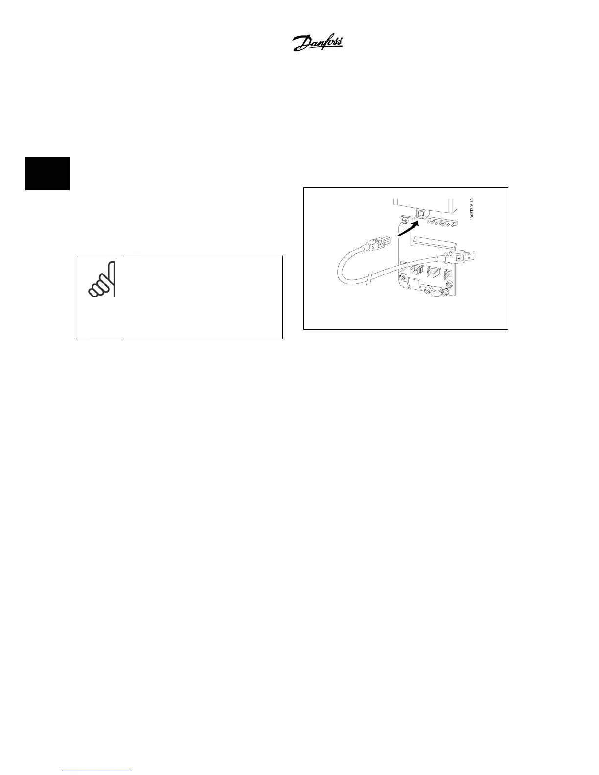
3.7.4 How to Connect a PC to the Adjustable Frequency Drive
To control the adjustable frequency drive from a PC, install the MCT 10
Set-up Software.
The PC is connected via a standard (host/device) USB cable or via the RS
485 interface as shown in the section
Bus Connection
in the Programming
Guide.
NOTE!
The USB connection is galvanically isolated from the
supply voltage (PELV) and other high-voltage termi-
nals. The USB connection is connected to protection
ground on the adjustable frequency drive. Use only
isolated laptop for PC connection to the USB connector
on the adjustable frequency drive.
Figure 3.23: USB connection.
3.7.5 The FC 300 PC software
Data storage in PC via MCT 10 Set-up Software:
1. Connect a PC to the unit via the USB com port.
2. Open MCT 10 Set-up Software
3. Select the USB port in the “network” section.
4. Choose “Copy”.
5. Select the “project” section.
6. Choose “Paste”.
7. Choose “Save as”
All parameters are now stored.
Data transfer from PC to drive via MCT 10 Set-up Software:
1. Connect a PC to the unit via the USB com port.
2. Open MCT 10 Set-up software
3. Choose “Open”– stored files will be shown.
4. Open the appropriate file
5. Choose “Write to drive”
All parameters are now transferred to the drive.
A separate manual for MCT 10 Set-up Software is available.
3 How to Install
VLT
®
AutomationDrive FC 300 Instruction
Manual
3-30
MG.33.AG.22 - VLT
®
is a registered Danfoss trademark
3
 Loading...


