EasyManuals Logo
Home>Danfoss>DC Drives>VLT AutomationDrive FC 300

Danfoss VLT AutomationDrive FC 300 Instruction Manual

Danfoss VLT AutomationDrive FC 300
120 pages
To Next Page IconTo Next Page
To Previous Page IconTo Previous Page
Page #36 background imageLoading...
Page #36 background image
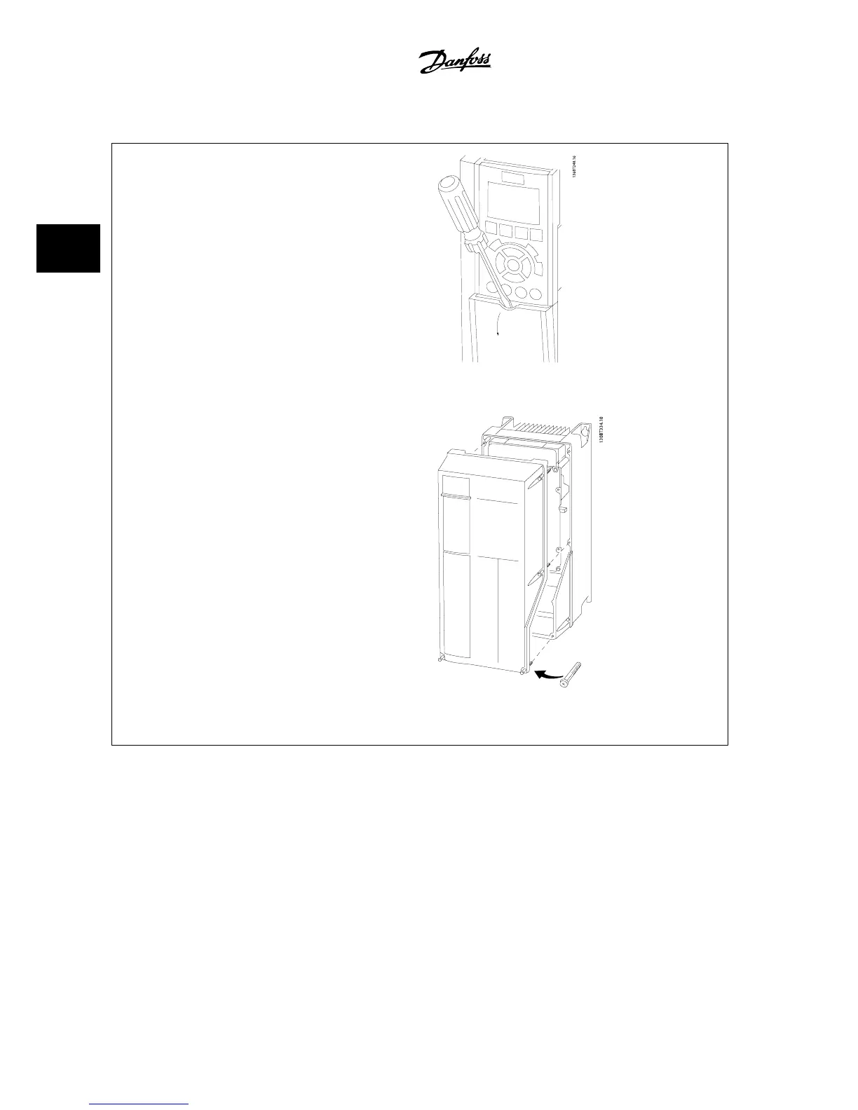
3.3.6 Access to Control Terminals
All terminals to the control cables are located underneath the terminal cover
on the front of the adjustable frequency drive. Remove the terminal cover
with a screwdriver.
Figure 3.20: Access to control terminals for A2, A3, B3, B4, C3 and
C4 enclosures
Remove front cover to access control terminals. When replacing the front
cover, ensure proper fastening by applying a torque of 2 Nm.
Figure 3.21: Access to control terminals for A4, A5, B1, B2, C1 and
C2 enclosures
3 How to Install
VLT
®
AutomationDrive FC 300 Instruction
Manual
3-20
MG.33.AG.22 - VLT
®
is a registered Danfoss trademark
3

Table of Contents

Other manuals for Danfoss VLT AutomationDrive FC 300

Questions and Answers:

Question and Answer IconNeed help?

Do you have a question about the Danfoss VLT AutomationDrive FC 300 and is the answer not in the manual?

Danfoss VLT AutomationDrive FC 300 Specifications

General IconGeneral
BrandDanfoss
ModelVLT AutomationDrive FC 300
CategoryDC Drives
LanguageEnglish

Related product manuals