WARNING/ALARM 28, Brake check failed
The brake resistor is not connected or not working.
Check parameter 2-15 Brake Check.
ALARM 29, Heatsink temp
The maximum temperature of the heatsink has been
exceeded. The temperature fault resets when the
temperature falls below a dened heatsink temperature.
The trip and reset points are dierent based on the
adjustable frequency drive power size.
Troubleshooting
Check for the following conditions.
•
Ambient temperature too high.
•
Motor cables too long.
•
Incorrect airow clearance above and below the
adjustable frequency drive
•
Blocked airow around the adjustable frequency
drive.
•
Damaged heatsink fan.
•
Dirty heatsink.
For the D, E, and F enclosures, this alarm is based on the
temperature measured by the heatsink sensor mounted
inside the IGBT modules. For the F enclosures, the thermal
sensor in the rectier module can also cause this alarm.
Troubleshooting
•
Check fan resistance.
•
Check soft charge fuses.
•
IGBT thermal sensor.
ALARM 30, Motor phase U missing
Motor phase U between the adjustable frequency drive
and the motor is missing.
Troubleshooting
•
Remove the power from the adjustable frequency
drive and check motor phase U.
ALARM 31, Motor phase V missing
Motor phase V between the adjustable frequency drive
and the motor is missing.
Troubleshooting
•
Remove the power from the adjustable frequency
drive and check motor phase V.
ALARM 32, Motor phase W missing
Motor phase W between the adjustable frequency drive
and the motor is missing.
Troubleshooting
•
Remove the power from the adjustable frequency
drive and check motor phase W.
ALARM 33, Inrush fault
Too many power-ups have occurred within a short time
period.
Troubleshooting
•
Let the unit cool to operating temperature.
WARNING/ALARM 34, Fieldbus communication fault
The serial communication bus on the communication
option card is not working.
WARNING/ALARM 36, Mains failure
This warning/alarm is only active if the supply voltage to
the adjustable frequency drive is lost and
parameter 14-10 Mains Failure is not set to option [0] No
Function. Check the fuses to the adjustable frequency drive
and line power supply to the unit.
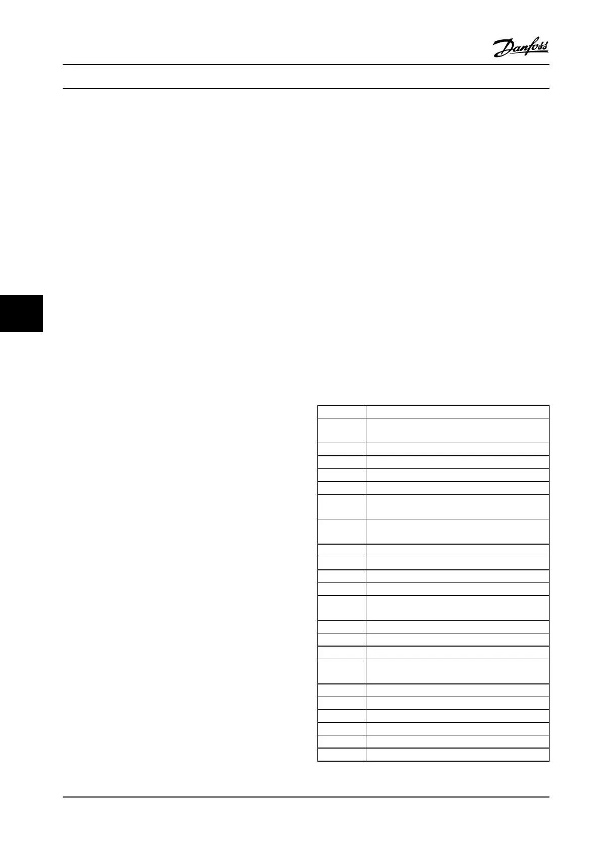
ALARM 38, Internal fault
When an internal fault occurs, a code number dened in
Table 7.1 is displayed.
Troubleshooting
•
Cycle power
•
Check that the option is properly installed
•
Check for loose or missing wiring
It may be necessary to contact Danfoss service or the
supplier. Note the code number for further troubleshooting
directions.
No. Text
0 Serial port cannot be initialized. Contact your
Danfoss supplier or Danfoss Service Department.
256–258 Power EEPROM data is defective or too old
512 Control board EEPROM data is defective or too old.
513 Communication timeout reading EEPROM data
514 Communication timeout reading EEPROM data
515 Application-oriented control cannot recognize the
EEPROM data.
516 Cannot write to the EEPROM because a write
command is on progress.
517 Write command is under timeout
518 Failure in the EEPROM
519 Missing or invalid barcode data in EEPROM
783 Parameter value outside of min/max limits
1024–1279 A CAN message that has to be sent could not be
sent.
1281 Digital signal processor ash timeout
1282 Power micro software version mismatch
1283 Power EEPROM data version mismatch
1284 Cannot read digital signal processor software
version
1299 Option SW in slot A is too old
1300 Option SW in slot B is too old
1301 Option SW in slot C0 is too old
1302 Option SW in slot C1 is too old
1315 Option SW in slot A is not supported (not allowed)
1316 Option SW in slot B is not supported (not allowed)
Status Messages
VLT
®
AutomationDrive FC 302 Low Harmonic Drive
132–630 kW
72 Danfoss A/S © Rev. 04/2015 All rights reserved. MG37A322
77
 Loading...


