2.4.5.9 Mechanical Brake Control
In hoisting/lowering applications, it is necessary to be able
to control an electro-mechanical brake:
•
Control the brake using any relay output or
digital output (terminal 27 or 29).
•
Keep the output closed (voltage-free) as long as
the Adjustable frequency drive is unable to
‘support’ the motor, for example due to the load
being too heavy.
•
Select Mechanical brake control [32] in par. 5-4*
for applications with an electro-mechanical brake.
•
The brake is released when the motor current
exceeds the preset value in 2-20 Release Brake
Current.
•
The brake is engaged when the output frequency
is less than the frequency set in 2-21 Activate
Brake Speed [RPM]or 2-22 Activate Brake Speed
[Hz], and only if the Adjustable frequency drive
carries out a stop command.
If the Adjustable frequency drive is in alarm mode or in an
overvoltage situation, the mechanical brake immediately
cuts in.
In the vertical movement, the key point is that the load
must be held, stopped, controlled (raised, lowered) in a
perfectly safe mode during the entire operation. Because
the Adjustable frequency drive is not a safety device, the
crane/lift designer (OEM) must decide on the type and
number of safety devices (e.g., speed switch, emergency
brakes, etc.) to be used in order to be able to stop the
load in case of emergency or malfunction of the system,
according to relevant national crane/lift regulations.
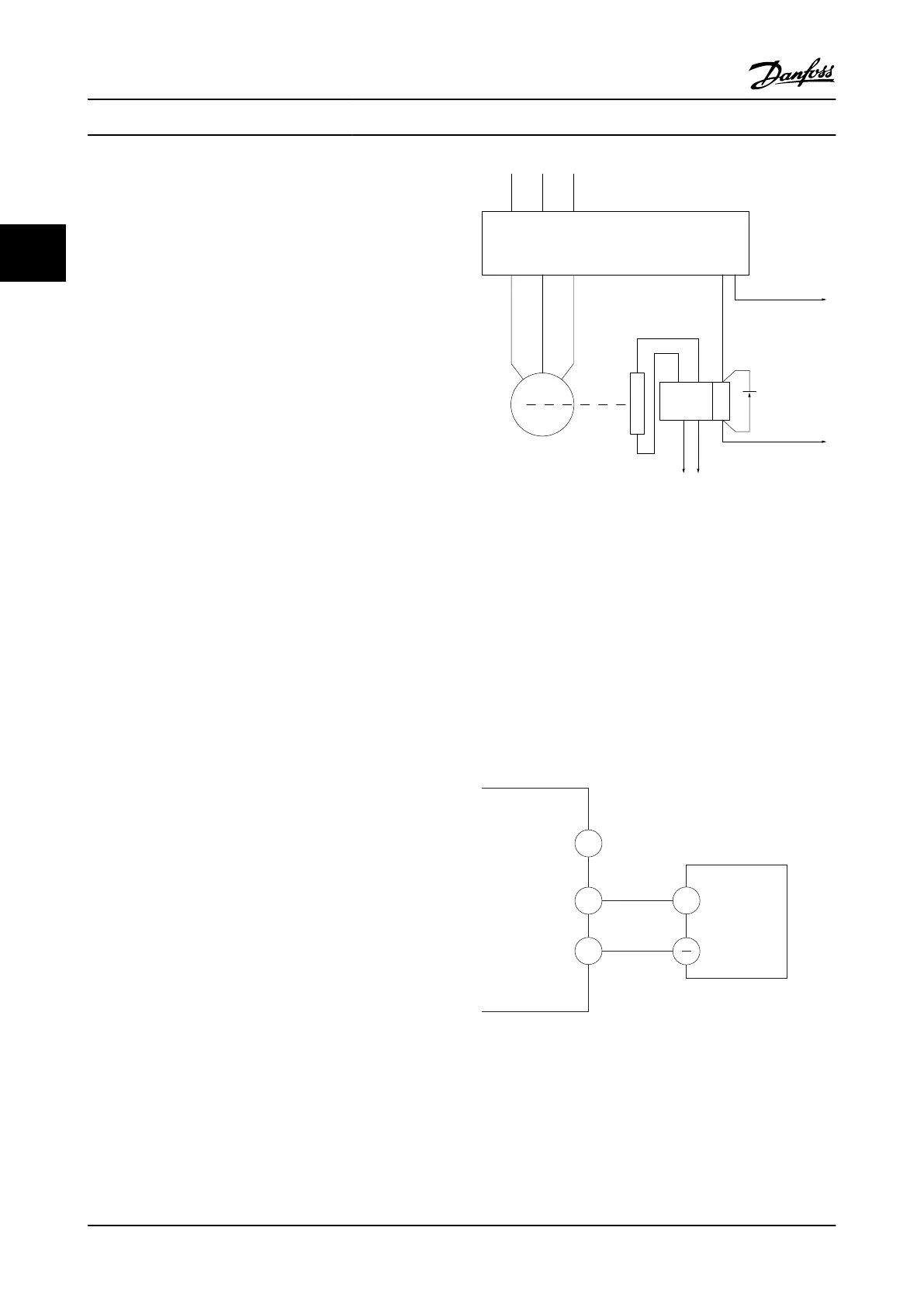
L1 L2 L3
U V W
02 01
A1
A2
130BA902.10
Drive
Output
relay
Command Circuit
220Vac
Mechanical
Brake
Shaft
Motor
Frewheeling
diode
Brake
380Vac
Output
Contactor
Input
Power Circuit
Figure 2.17 Connecting the Mechanical Brake to the Adjustable
Frequency Drive
2.4.6
Serial Communication
Connect RS-485 serial communication wiring to terminals
(+)68 and (-)69.
•
A shielded serial communication cable is
recommended
•
See 2.4.2 Grounding Requirements for proper
grounding
61
68
69
+
130BB489.10
RS-485
Figure 2.18 Serial Communication Wiring Diagram
Installation
VLT
®
AutomationDrive Instruction
Manual
2-14 MG.33.AI.22 - VLT
®
is a registered Danfoss trademark
2
2
 Loading...


