1
2
3
4
5
6
7
8
9
10
11
12
13
16
17
18
19
14
15
FAN MOUNTING
QDF-30
DC-
DC+
Remove jumper to activate Safe Stop
Max. 24 Volt !
12
13
18
19 27 29 32
33
20
61
68
39
42
50
53 54
06 05 04
03 02 01
130BB493.10
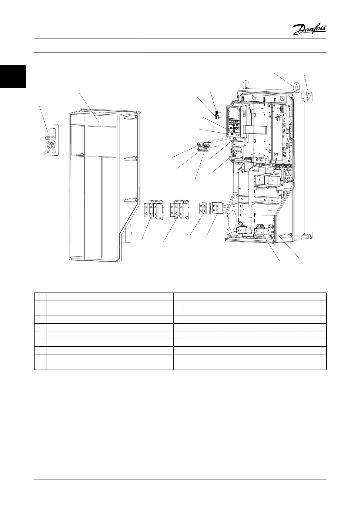
Figure 1.2 Exploded View B and C Sizes, IP55/66
1
LCP 11 Relay 2 (04, 05, 06)
2 Cover 12 Lifting ring
3 RS-485 serial bus connector 13 Mounting slot
4 Digital I/O and 24 V power supply 14 Grounding clamp (PE)
5 Analog I/O connector 15 Cable strain relief / PE ground
6 Cable strain relief / PE ground 16 Brake terminal (-81, +82)
7 USB connector 17 Load sharing terminal (DC bus) (-88, +89)
8 Serial bus terminal switch 18 Motor output terminals 96 (U), 97 (V), 98 (W)
9 Analog switches (A53), (A54) 19 Line power input terminals 91 (L1), 92 (L2), 93 (L3)
10 Relay 1 (01, 02, 03)
1.1 Purpose of the Manual
This manual is intended to provide detailed information for
the installation and start-up of the adjustable frequency
drive. Chapter 2 Installation provides requirements for
mechanical and electrical installation, including input,
motor, control and serial communications wiring, and
control terminal functions. Chapter 3 Start-up and
Functional Testing provides detailed procedures for start-
up, basic operational programming, and functional testing.
The remaining chapters provide supplementary details.
These include user interface, detailed programming,
application examples, start-up troubleshooting, and specifi-
cations.
1.2 Additional Resources
Other resources are available to understand advanced
Adjustable frequency drive functions and programming.
Introduction
VLT
®
AutomationDrive Instruction
Manual
1-2 MG.33.AI.22 - VLT
®
is a registered Danfoss trademark
11
 Loading...


