Design Guide | VLT® AutomationDrive FC 360
Select [3] Process in parameter 1-00 Configuration Mode to use the process PID control for closed-loop control of speed or pressure in
the controlled application. The process PID parameters are in parameter groups 7-2* Process Ctrl. Feedb and parameter groups 7-3*
Process PID Ctrl.
8.3.4.2 Control Structure in Flux Sensorless
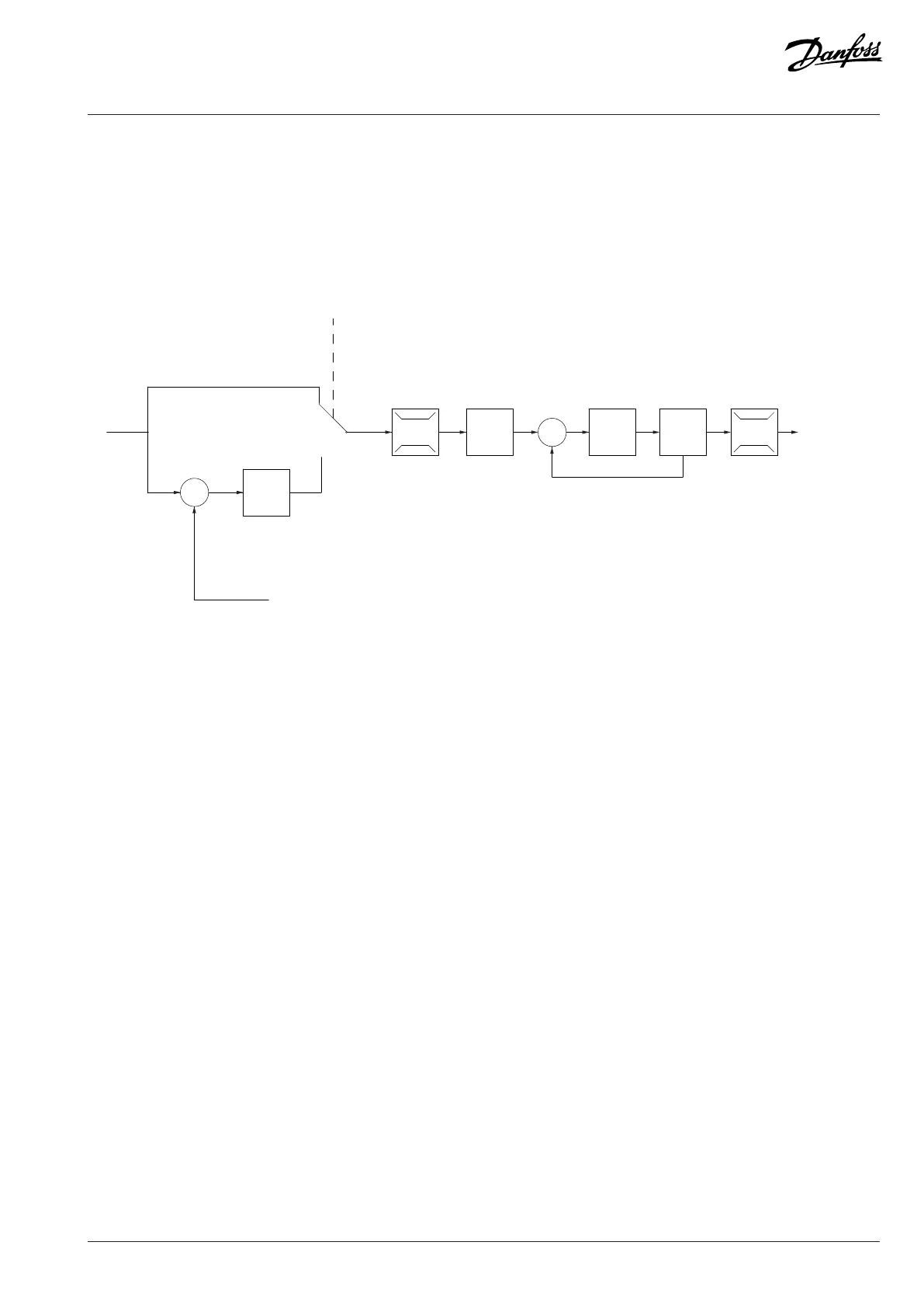
Control structure in Flux Sensorless open-loop and closed-loop configurations.
P 7-22 Process feedback
2 source
Max. output
freq.
Motor
controller
-f max.
Speed
PID
P 7-0*
Figure 47: Control Structure in Flux Sensorless
In the configuration shown, parameter 1-01 Motor Control Principle is set to [2] Flux Sensorless and parameter 1-00 Configuration Mode
is set to [0] Speed open loop. The resulting reference from the reference handling system is fed through the ramp and speed limitations
as determined by the parameter settings indicated.
An estimated speed feedback is generated to the speed PID to control the output frequency.
The speed PID must be set with its P, I, and D parameters (parameter group 7-0* Controllers).
Select [3] Process in parameter 1-00 Configuration Mode to use the process PID control for closed-loop control of speed or pressure
in the controlled application. The process PID parameters are in parameter group 7-2* Process Ctrl. Feedb and parameter group 7-3*
Process PID Ctrl.
8.3.4.3 Control Structure in Flux with Motor Feedback
Danfoss A/S © 2024.01 AJ435824192086en-000101 / 130R1295 | 87
 Loading...


