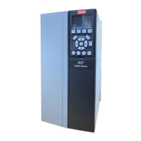
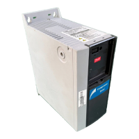
Insulation monitor (-BE1)
Local control panel (LCP)
RJ45 terminal blocks 1 and 2 (-RJ45_1 and RJ45_2)
Protection terminal block set (-XD11)
Contactor control circuit terminal block (-XD0)
Cabinet heater terminal block (-XD4)
Customer terminal block/option C0 terminal block (-
XDW)
Thermal trip indicator relay, input power options
cabinet (-KFJ.1)
Thermal trip indicator relay, output filter cabinet (-
KFJ.2)
Thermal trip indicator relay, input filter cabinet (-
KFJ.3)
PHF capacitor connect/disconnect contactor relay (-
QAF)
+24 DC supply protection MCB (-FC7)
AC circuit protection MCB (-FC6)
AC distribution circuit terminal block (-XD1)
Auxiliary relay for heater (-QAM)
Contactor control circuit protection MCB (-FC10)
Cabinet light/socket outlet protection MCB (-FCC)
Cabinet heater(s) circuit protection MCB (-FCE)
DC distribution circuit terminal block (-XD3)
Motor heater circuit protection MCB (-FCN)
AC fan supply terminal block set (-XDY)
Option C2 terminal block set (-XDF)
Basic I/O terminal block and option A, B, D card ter-
minal block set (-XD2)
Door components terminal block set (-XDJ)
Grounding clamp for the shield termination of wires
5.7.3 Control Terminals
Table 43: Serial Communication Terminals
Integrated RC-filter for cable shield. Used only for connecting the shield in
case of EMC problems.
Parameter group 8-3* FC
Port Settings
RS485 interface. A switch (BUS TER.) is provided on the control card for bus
termination resistance. See Illustration 5.22.
Parameter group 8-3* FC
Port Settings
Table 44: Digital Input/Output Terminal Descriptions
24 V DC supply voltage for digital inputs and external trans-
ducers. Maximum output current 200 mA for all 24 V loads.
Parameter 5-10 Terminal 18 Digital
Input
Parameter 5-11 Terminal 19 Digital
Input
Parameter 5-14 Terminal 32 Digital
Input
AQ262139143212en-000301 / 130R0879 | 83Danfoss A/S © 2021.10
Electrical Installation
VLT® AutomationDrive FC 302
Operating Guide
 Loading...


