3.4.3 Gland/Conduit Entry - IP21 (NEMA 1)
and IP54 (NEMA 12)
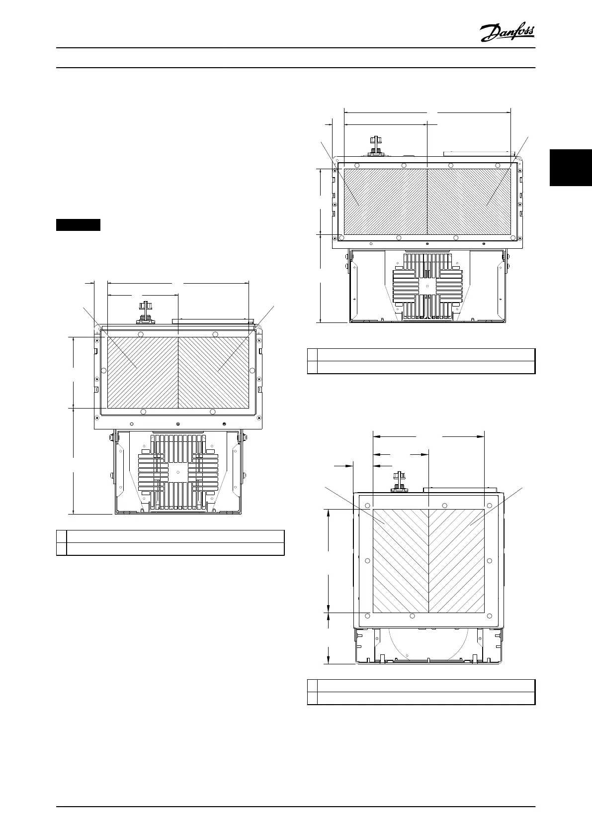
Cables are connected through the gland plate from the
bottom. Remove the plate and plan where to place the
entry for the glands or conduits. Illustration 3.29 to
Illustration 3.33 show the cable entry points viewed from
the bottom of various frequency converters.
NOTICE
Fit the gland plate to the frequency converter to ensure
the specified protection degree.
130BC521.10
205
[8.1]
138
[5.4]
274
[10.8]
27
[1.0]
137
[5.4]
1
2
1 Mains side
2 Motor side
Illustration 3.29 D1h, Bottom View
130BC524.11
196
[7.7]
145
[5.7]
27
[1.0]
185
[7.3]
1
2
369
[14.5]
1
Mains side
2 Motor side
Illustration 3.30 D2h, Bottom View
111
[4.4]
224
[8.8]
242
[9.5]
121
[4.8]
43
[1.7]
1
2
130BC550.11
1
Mains side
2 Motor side
Illustration 3.31 D5h & D6h, Bottom View
Installation Operating Instructions
MG16J202 Danfoss A/S © Rev. 05/2014 All rights reserved. 31
3 3
 Loading...


