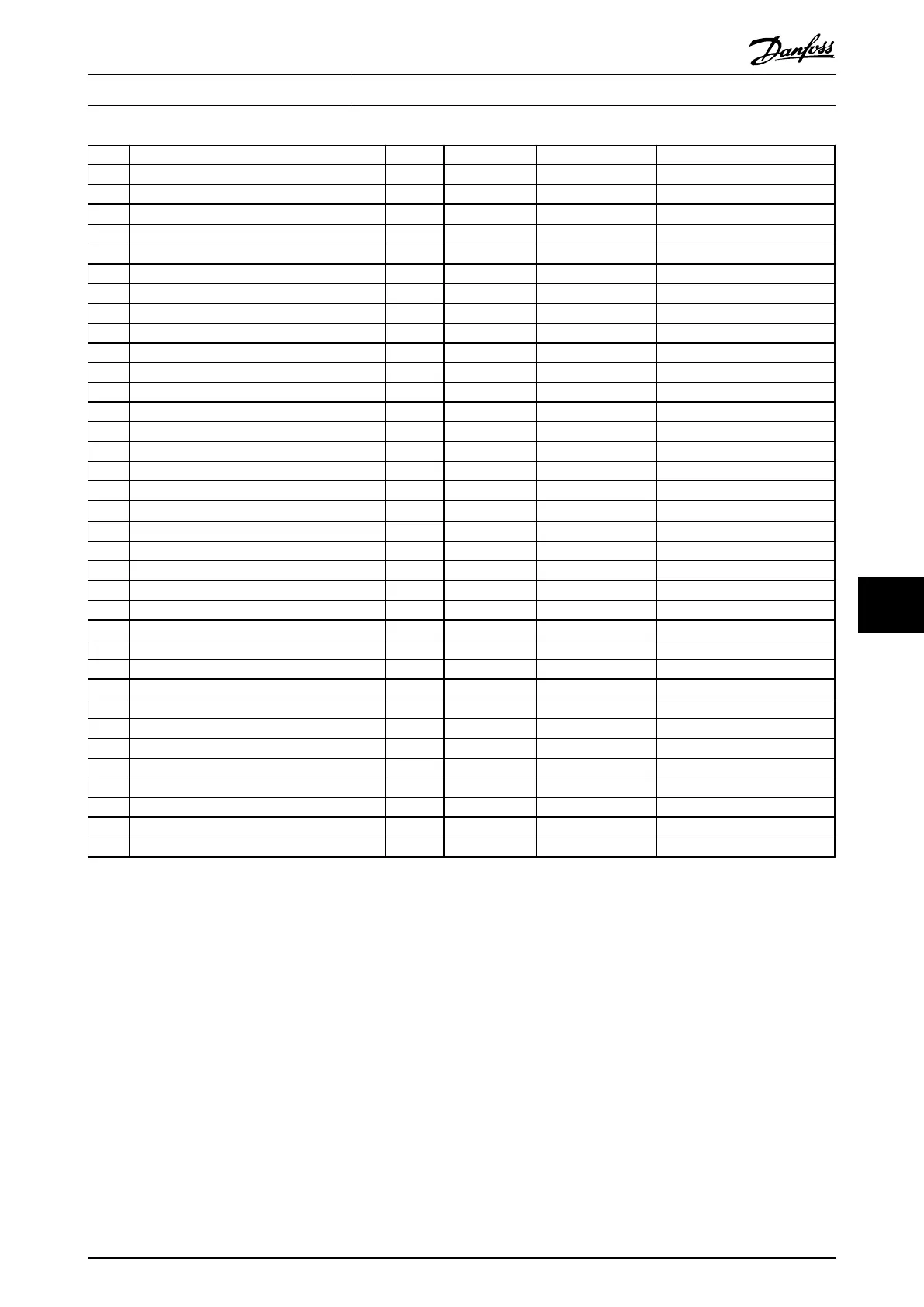
No. Description Warning Alarm/Trip Alarm/Trip lock Parameter reference
49 Speed limit X (X) 1-86 Trip Speed Low [RPM]
50 AMA calibration failed X
51 AMA check U
nom
and I
nom
X
52 AMA low I
nom
X
53 AMA motor too big X
54 AMA motor too small X
55 AMA Parameter out of range X
56 AMA interrupted by user X
57 AMA timeout X
58 AMA internal fault X X
59 Current limit X
60 External Interlock X
62 Output Frequency at Maximum Limit X
64 Voltage Limit X
65 Control board overtemperature X X X
66 Heat sink Temperature Low X
67 Option Configuration has Changed X
68
Safe Stop
1)
(X) (X)
5-19 Terminal 37 Digital Input
69 Pwr.card temp X X
70 Illegal FC configuration X
77 Reduced Power Mode
79 Illegal PS config X X
80 Drive Initialized to Default Value X
91 Analog input 54 wrong settings X
92 NoFlow X X 22-2* No-Flow Detection
93 Dry Pump X X 22-2* No-Flow Detection
94 End of Curve X X 22-5* End of Curve
95 Broken Belt X X 22-6* Broken Belt Detection
96 Start Delayed X 22-7* Short Cycle Protection
97 Stop Delayed X 22-7* Short Cycle Protection
98 Clock Fault X 0-7* Clock Settings
99 Locked rotor
104 Mixing Fan Fault X X
14-53 Fan Monitor
250 New spare parts X
251 New Type Code X X
Table 9.1 Alarm/Warning Code List
(X) Dependent on parameter
1)
Cannot be Auto reset via 14-20 Reset Mode
9.5
Fault Messages
The following warning/alarm information defines each
warning/alarm condition, provides the probable cause for
the condition, and details a remedy or troubleshooting
procedure.
WARNING 1, 10 Volts low
The control card voltage is below 10 V from terminal 50.
Remove some of the load from terminal 50, as the 10 V
supply is overloaded. Max. 15 mA or minimum 590 Ω.
This condition can be caused by a short in a connected
potentiometer or improper wiring of the potentiometer.
Troubleshooting
•
Remove the wiring from terminal 50. If the
warning clears, the problem is with the customer
wiring. If the warning does not clear, replace the
control card.
WARNING/ALARM 2, Live zero error
This warning or alarm only appears if programmed by the
user in 6-01 Live Zero Timeout Function. The signal on one
of the analog inputs is less than 50% of the minimum
value programmed for that input. Broken wiring or faulty
device sending the signal can cause this condition.
Warnings and Alarms Operating Instructions
MG16J202 Danfoss A/S © Rev. 05/2014 All rights reserved. 85
9 9
 Loading...


