VLT
®
FCD Series
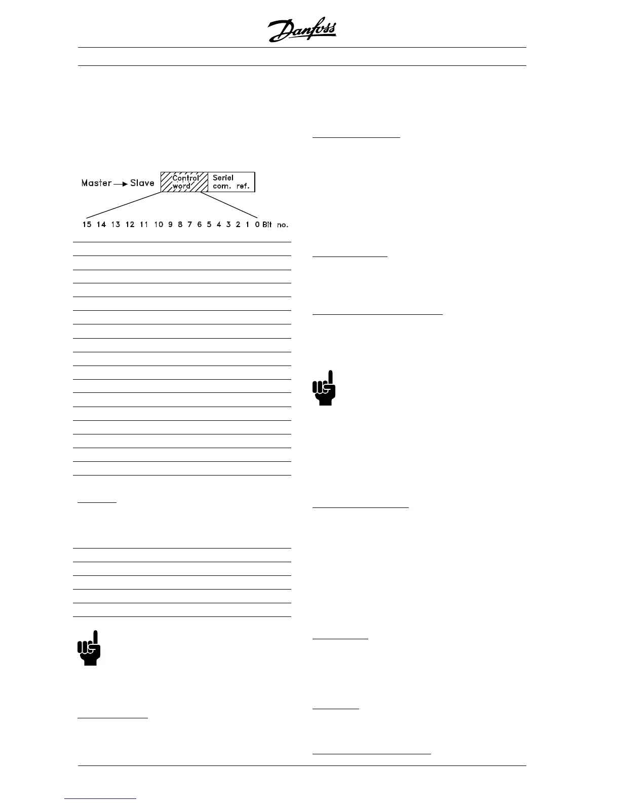
■ Control Word according toFC protocol
To select FC protocol in the control word, parameter
512 Telegram Profile must be set to FC protocol [1].
The control word is used to send commands from a
master (e.g. a PC) to a slave (frequency converter).
Bit Bit = 0 Bit =1
00 Preset ref. lsb
01 Preset ref. msb
02 DC braking
03 Coasting stop
04 Quick stop
05 Freeze outp. freq.
06 Ramp stop Start
07 Reset
08 Jog
09 Ramp 1 Ramp 2
10 Data not valid Data valid
11 No function
12 No function
13 Select Setup, lsb
14 Select Setup, msb
15 Reversing
Bit 00/01:
Bit 00/01 is used to select between the two pre-
programmed references (parameters 215-218 Preset
reference) according to the following table:
Preset ref. Parameter Bit 01 Bit 00
1 215 0 0
2 216 0 1
3 217 1 0
4 218 1 1
NB!:
In parameter 508 Selection of preset refer-
ence a selection is made to define how Bit 00/
01 gates with the corresponding function on the digi-
tal inputs.
B
it 02, DC brake:
Bit 02 = ’0’ causes DC braking and stop. Brake volt-
age and duration are preset in parameters 132 DC
brake voltage and parameter 126 DC braking time.
Note: In parameter 504 DC brake a selection is
made to define how Bit 02 gates with the corre-
sponding function on a digital input.
B
it 03, Coasting stop:
Bit 03 = ’0’ causes the frequency converter to imme-
diately "let go" of the motor (the output transistors
are "shut off"), so that it coasts to a standstill.
Bit 03 = ’1’ causes the frequency converter to be
able start the motor if the other starting conditions
have been fulfilled. Note: In parameter 502 Coasting
stop a selection is made to define how Bit 03 gates
with the corresponding function on a digital input.
B
it 04, Quick stop:
Bit 04 = ’0’ causes a stop, in which the motor’s
speed is ramped down to stop via parameter 212
Quick stop ramp-down time.
B
it 05, Freeze output frequency:
Bit 05 = ’0’ causes the present output frequency (in
Hz) to freeze. The frozen output frequency can now
only be changed by means of the digital inputs pro-
grammed to Speed up and Speed down.
NB!:
If Freeze output is active, the frequency con-
verter cannot be stopped via Bit 06 Start or
via a digital input. The frequency converter can only
be stopped by the following:
• Bit 03 Coasting stop
• Bit 02 DC braking
• Digital input programmed to DC braking, Coasting
stop or Reset and coasting stop.
B
it 06, Ramp stop/start:
Bit 06 = ’0’ causes a stop, in which the motor’s
speed is ramped down to stop via the selected ramp
down parameter.
Bit 06 = ’1’ causes the frequency converter to be
able to start the motor, if the other starting condi-
tions have been fulfilled. Note: In parameter 505
Start a selection is made to define how Bit 06 Ramp
stop/start gates with the corresponding function on a
digital input.
B
it 07, Reset:
Bit 07 = ’0’ does not cause a reset.
Bit 07 = ’1’ causes the reset of a trip. Reset is acti-
vated on the signal’s leading edge, i.e. when
changing from logic ’0’ to logic ’1’.
B
it 08, Jog:
Bit 08 = ’1’ causes the output frequency to be deter-
mined by parameter 213 Jog frequency.
B
it 09, Selection of ramp 1/2:
MG.04.A1.02 - VLT is a registered Danfoss trade mark
100
 Loading...


