VLT
®
FCD Series
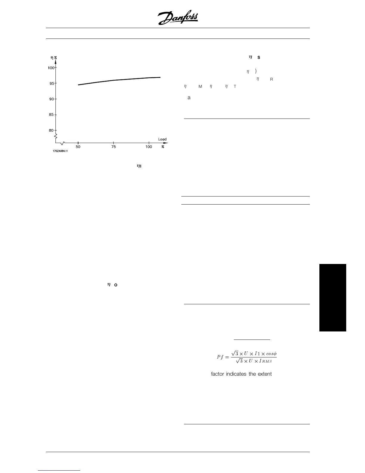
Efficiency of frequency converters (
INV
)
The load on the frequency converter has little effect
on its efficiency. In general, the efficiency is the
same at the rated motor frequency f
M,N
, regardless
of whether the motor supplies 100% rated shaft
torque or only 75%, e.g. in case of part loads.
This also means that the efficiency of the frequency
converter does not change even if other U/f charac-
teristics are chosen. However, the U/f characteristics
influence the efficiency of the motor.
The efficiency declines a little when the switching
frequency is set to a value above 4.5 kHz (parame-
ter 411
Switching frequency). The rate of efficiency
will also be slightly reduced at a high mains voltage
(480 V).
Efficiency of the motor (
MOTOR
)
The efficiency of a motor connected to the frequency
converter depends on the sine shape of the current.
In general, the efficiency is just as good as in mains
operation. The efficiency of the motor depends on
the motor type.
In the range of 75-100% of the rated torque, the effi-
ciency of the motor is practically constant, both
when it is controlled by the frequency converter and
when it runs directly on mains.
In general, the switching frequency does not affect
the efficiency of small motors.
Efficiency of the system (
SYSTEM
)
To calculate the system efficiency, the efficiency of
the frequency converters (
INV
) should be multiplied
by the efficiency of the motor (
MOTOR
):
SYSTEM
=
INV
x
MOTOR
.
Based on the graph above, it is possible to calculate
the system efficiency at different loads.
■ Mains supply interference/harmonics
A frequency converter takes up a non-sinusoidal cur-
rent from mains, which increases the input current
I
RMS
. A non-sinusoidal current can be transformed
by means of a Fourier analysis and split up into
sinusoidal currents with different frequencies, i.e. dif-
ferent harmonic currents I
n
with 50 Hz as the basic
frequency:
Harmonic currents I
1
I
5
I
7
Frequency [Hz] 50 250 350
The harmonic currents do not affect power con-
sumption directly, but they increase the heat losses
in the installation (transformer, cables). Conse-
quently, in plants with a rather high percentage of
rectifier load, it is important to maintain harmonic
currents at a low level to avoid overload of the trans-
former and high temperature in the cables.
Some of the harmonic currents might disturb com-
munication equipment connected to the same
transformer or cause resonance in connection with
power-factor correction batteries.
■ Power factor
The power factor (Pf) is the relation between I
1
and
I
RMS
.
The power factor for 3
-phase supply:
Pf
=
p
3
2
U
2
I
1
2
cos
p
3
2
U
2
I
RMS
The power factor indicates the extent to which the
frequency converter imposes a load on the mains
supply. The lower the power factor, the higher the
I
RMS
for the same kW performance. In addition, a
high power factor indicates that the different har-
monic currents are low.
MG.04.A1.02 - VLT is a registered Danfoss trade mark
121
All about FCD 300
 Loading...


