VLT
®
FCD Series
Description of choice:
A value can be selected from f
MIN
to the value cho-
sen in parameter 200 Output frequency range.
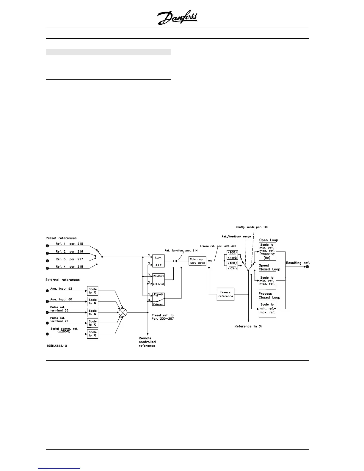
■ Handling of references
Handling of references is described in the block dia-
gram below. The block diagram shows how a change
in one parameter can affect the resulting reference.
Parameters 203 to 205 Reference and parameter
214 Reference function define how the handling of
references can be performed. The parameters men-
tioned can be active in both closed and open loop.
Remote controlled references are defined as:
- External references, such as analogue inputs 53
and 60, pulse references via terminal 33 and ref-
erences from serial communication.
- Preset references
The resulting reference can be shown on the LCP
control unit’s display by selecting Reference [%] in
parameters 009-012 Display readout and can be
shown as one unit by selecting Reference [unit].
The sum of the external references can be shown on
the LCP control unit’s display as a % of the area from
Minimum reference, Ref
MIN
to Maximum reference,
Ref
MAX
. Select External reference, % [25] in parame-
ters 009-012 Display readout if a readout is desired.
It is possible to have both references and external
references simultaneously . In parameter 214 Refer-
ence function a selection can be made to determine
how preset references should be added to the exter-
nal references.
There is also an independent local reference in pa-
rameter 003 Local reference, in which the resulting
reference is set using the [+/-] keys. When the local
reference has been selected, the output frequency
range is limited by parameter 201 Output frequency
low limit, f
MIN
and parameter 202 Output frequency
high limit, f
MAX
.
The local reference unit depends on the selection in
parameter 100 Configuration.
✭ = factory setting. () = display text [] = value for use in communication via serial communication port
MG.04.A1.02 - VLT is a registered Danfoss trade mark
66
 Loading...


