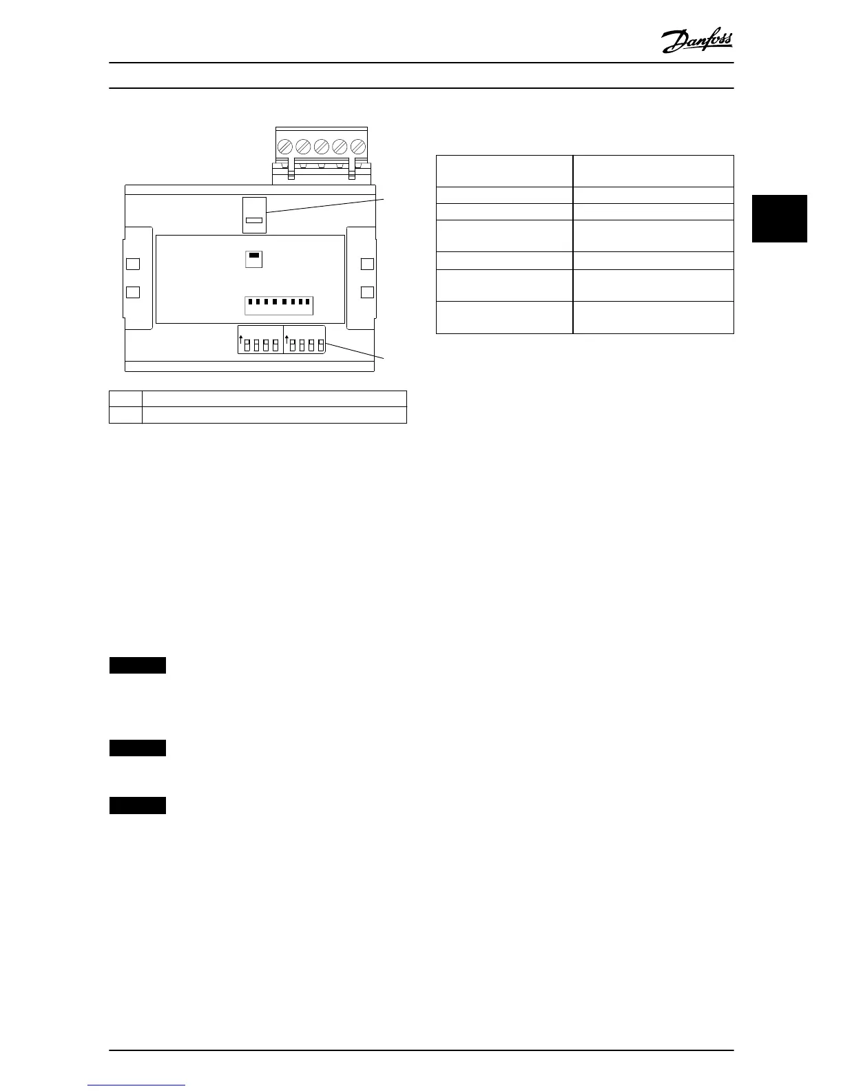
1 Termination switch
2 Address switches
Illustration 3.7 Location and Sequence of the Address Switches
3.7 Electrical Installation
3.7.1 Cabling Requirements
•
Terminate the nodes at the physical ends of each
segment. If the bus segment is branched, the
device furthest from the segment connector
represents the end of the segment.
•
Terminals 66 and 67 provide a 5 V DC supply,
available for external termination.
NOTICE
The PROFIBUS D-sub 9 adapter also features a
termination switch. When the D-sub 9 adapter is used,
set the termination switch on the eldbus option to OFF,
to avoid double termination.
NOTICE
When the eldbus is extended with a repeater, terminate
the extension at both ends.
NOTICE
To avoid impedance mismatch, use the same cable type
throughout the entire network. Refer to
chapter 3.7.2 Cable Specications for cable specications.
3.7.2 Cable Specications
Impedance at a measuring
frequency from 3–20 MHz
135–165 Ω
Resistance
<110 Ω/km
Capacitance <30 pF/m
Damping (total wire length) Maximum 9 dB over the whole
wire length
Cross-section
Maximum 0.34 mm
2
, AWG 22
Cable type Twisted in pairs, 1 x 2, 2 x 2, or
1 x 4 wires
Screening Copper-braided screen, or braided
screen and foil screen
Table 3.2 Cable Specications
Installation Installation Guide
MG33C602 Danfoss A/S © 07/2015 All rights reserved. 9
3 3

 Loading...


