3 Installation
3.1 Safety Instructions
See chapter 2 Safety for general safety instructions.
3.2 EMC-compliant Installation
To obtain an EMC-compliant installation, follow the
instructions provided in the relevant frequency converter
operating instructions and design guide. Refer to the
eldbus master manual from the PLC supplier for further
installation guidelines.
3.3 Grounding
•
Ensure that all stations connected to the eldbus
network are connected to the same ground
potential. When distances between the stations in
a eldbus network are long, connect the
individual station to the same ground potential.
Install equalising cables between the system
components.
•
Establish a grounding connection with low HF
impedance, for example by mounting the
frequency converter on a conductive back plate.
•
Keep the ground wire connections as short as
possible.
•
To establish electrical contact between the cable
screen and the frequency converter enclosure,
use metal cable glands or the clamps provided
on the equipment.
•
Use high-strand wire to reduce burst transient.
3.4
Cable Routing
NOTICE
EMC INTERFERENCE
Use screened cables for motor and control wiring, and
separate cables for eldbus communication, motor
wiring, and brake resistor. Failure to isolate eldbus
communication, motor, and brake resistor cables can
result in unintended behaviour or reduced performance.
Minimum 200 mm (7.9 in) clearance between power,
motor, and control cables is required. For power sizes
above 315 kW (450 hp), increase the minimum distance
of 500 mm (20 in).
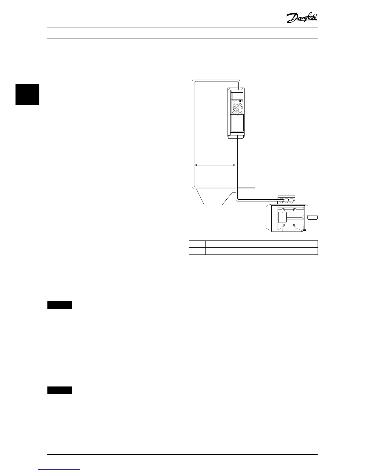
NOTICE
When the eldbus cable intersects a motor cable or a
brake resistor cable, ensure that the cables intersect at
an angle of 90°.
1 Fieldbus cable
2 90° intersection
Illustration 3.1 Cable Routing
3.5
Mounting
3.5.1 Mounting in an FC Series Frequency
Converter
1. Check whether the eldbus option is already
mounted in the frequency converter. If already
mounted, go to step 6. If not mounted, go to
step 2.
2. Remove the LCP or blind cover from the
frequency converter.
3. Use a screwdriver to remove the front cover and
the LCP cradle.
4. Mount the eldbus option. Mount the option
with the connector facing up for top cable entry
(see Illustration 3.3), or with the connector facing
down for bottom cable entry (see Illustration 3.4).
If an MCB option is installed, only top cable entry
is possible.
5. Remove the knock-out plate from the new LCP
cradle.
6. Mount the new LCP cradle.
Installation
VLT
®
PROFIBUS DP MCA 101
6 Danfoss A/S © 07/2015 All rights reserved. MG33C602
33

 Loading...


