4 Troubleshooting
4.1 Warnings and Alarms
NOTICE
Refer to the relevant operating instructions for an
overview of warning and alarm types and for the full list
of warnings and alarms.
Alarm word, warning word, and PROFIBUS warning word
are shown on the frequency converter display in hex
format. When there is more than 1 warning or alarm, the
sum of all warnings or alarms is shown. Alarm word,
warning word, and PROFIBUS warning word can also be
shown via eldbus in:
•
Parameter 16-90 Alarm Word.
•
Parameter 16-92 Warning Word.
•
Parameter 9-53 Probus Warning Word.
For warning 165, Baud rate search, refer to Table 4.1.
Bit (hex) Unit
diagnose
bit
PROFIBUS warning word
(parameter 9-53 Probus Warning
Word)
00000001 160 Connection with DP-master is not OK.
00000002 161 Unused
00000004 162 FDL (eldbus data link layer) is not
OK.
00000008 163 Clear data command received.
00000010 164 Actual value is not updated.
00000020 165 Baud rate search.
00000040 166 PROFIBUS ASIC is not transmitting.
00000080 167 Initialising of PROFIBUS is not OK.
00000100 152 Drive is tripped.
00000200 153 Internal CAN error.
00000400 154 Wrong conguration data from PLC.
00000800 155 Wrong ID sent by PLC.
00001000 156 Internal error occurred.
00002000 157 Not congured.
00004000 158 Timeout active.
00008000 159 Warning 34 active.
Table 4.1 Parameter 9-53 Probus Warning Word
4.2
Troubleshooting
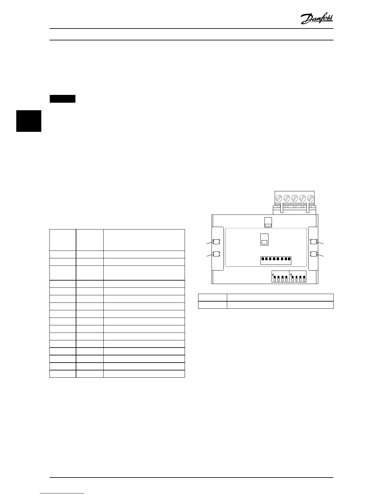
4.2.1 LED Status
The 2 bicolour LEDs on the PROFIBUS card indicate the
status of PROFIBUS communication:
•
The lower LED (NS) indicates the net status, that
is, the cyclic communication to the PROFIBUS
master.
•
The upper LED (MS) indicates the module status,
that is, acyclic DP-V1 communication from either
a PROFIBUS master class 1 (PLC) or a master class
2 (MCT 10 Set-up Software, FDT tool).

 Loading...


