7. Open the latch, and disconnect the fingerprint reader-board cable from the system board.
8. Remove the two screws (M2x4) that secure the USB Type-C bracket to the palm-rest and keyboard assembly.
9. Lift the USB Type-C bracket from the palm-rest and keyboard assembly.
10. Open the latch, and disconnect the keyboard-control board cable the system board.
11. Remove the two screws (M2x4) that secure the system board to the palm-rest and keyboard assembly.
NOTE: The thermal plate is a part of the system board, DO NOT separate it from the system board.
12. Lift the system board off the palm-rest and keyboard assembly.
NOTE: When handling the system board, hold the system board firmly at the top and bottom. DO NOT hold the system
board at the thin areas on the sides at the left and right.
Installing the system board
Prerequisites
If you are replacing a component, remove the existing component before performing the installation procedure.
NOTE: The Service Tag of your computer is stored in the system board. Enter the Service Tag in the BIOS setup program
after you replace the system board.
NOTE: Replacing the system board removes any changes that you have made to the BIOS using the BIOS setup program.
Make the appropriate changes again after you replace the system board.
NOTE: Replacing the system board removes any changes that you have made to the BIOS using the BIOS setup program.
Make the appropriate changes again after you replace the system board. After your computer is reassembled and turned on,
it prompts for the Real Time Clock (RTC) reset. When the RTC reset cycle occurs, the computer restarts several times and
then an error message is displayed- "Time of day not set". Enter the BIOS when this error appears and set the date and
time on your computer to resume normal functionality.
About this task
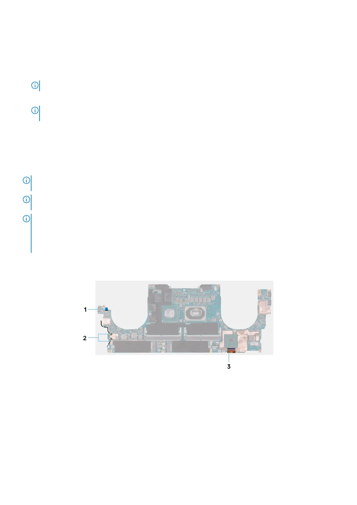
The following image indicates the connectors on your system board.
Figure 2. System-board connectors
1. Fingerprint reader-board cable
2. Antenna cables
3. Keyboard control-board cable
The following images indicate the location of the system board and provide a visual representation of the installation procedure.
Removing and installing components
43
 Loading...