AS Series Module Manual
11-14
Input/output
Table
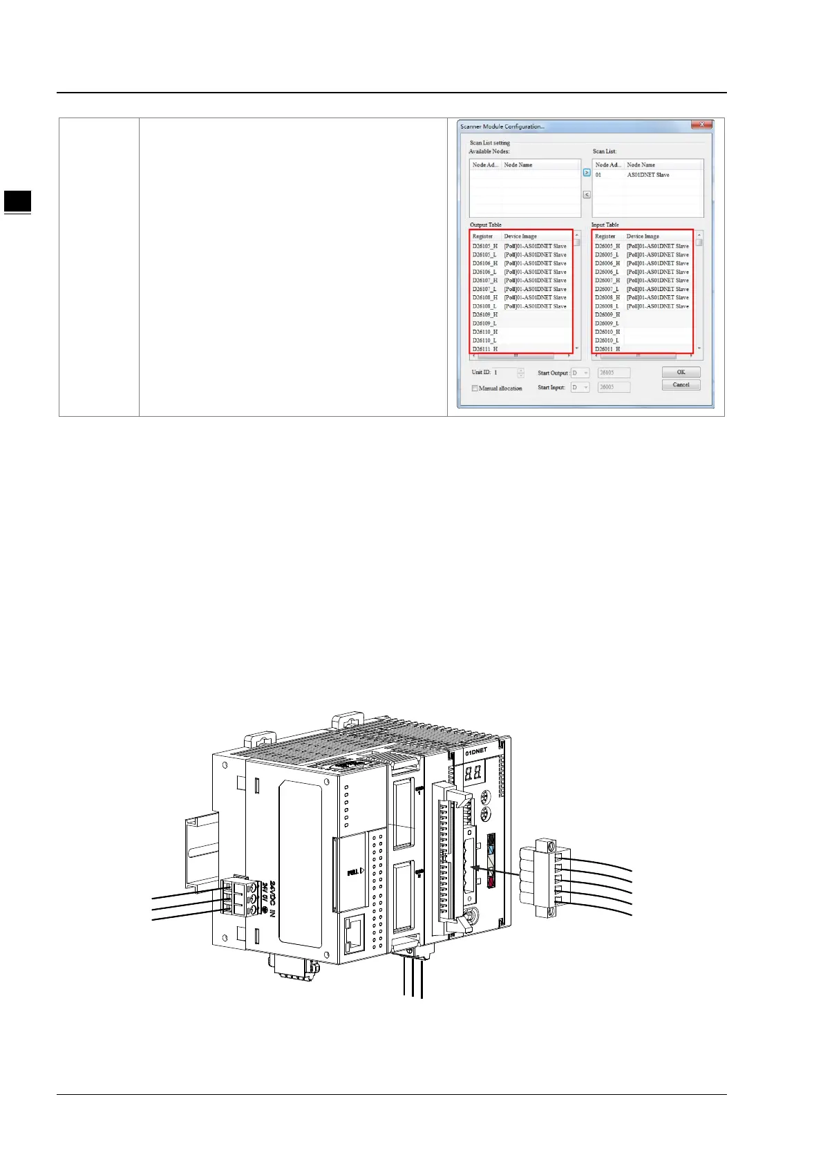
The scanner module provides an input table of total
size: 190 bytes and an output table of total size: 190
bytes for data exchange with slaves. When one slave
is configured to the scan list, the configuration
software will automatically assign corresponding size
of I/O data exchange area to the slave. Input Table
and Output Table are the interface for data exchange
between the PLC of the master and slaves and show
the mapping relationships between the D registers in
the PLC of the master and the I/O data of slaves.
After the configuration is finished, download the
configuration data to the scanner module. Then the
module will exchange I/O data with corresponding
slaves according to the configuration. The data in the
output table will be transmitted to slaves and the data
returned from slaves will be filled in the input table.
11.4.2 Installation
11.4.2.1. Connecting AS01DNET-A Module to AS series PLC
For the details on how AS01DNET-A (in Master/slave mode) is connected to AS series PLC, refer to Section 1.3.1
Installing a Module in AS Series Module Manual.
11.4.2.2. Connecting the DeviceNet Communication Connector
Make sure that the color marks for the PINs of the DeviceNet connection port match the colors of the connection
cables and the cable should be connected to the right PIN.
Delta’s power module is recommended as the power module in the communication.
 Loading...