EasyManua.ls Logo

Delta ASD-A2R-0221 Series User Manual

Delta ASD-A2R-0221 Series
660 pages
To Next Page IconTo Next Page
To Previous Page IconTo Previous Page
Page #218 background imageLoading...
Page #218 background image
Chapter 7 Motion Control ASDA-A2R Series
7-24 Revision December, 2014
7.10.1 The Relation between the Previous Path and the Next Path
1) Interrupt (the previous path) and overlap (the next path) can be set in every path
Note: Path (procedure)
2) The priority of interrupt command is higher than overlap
PATH 1 PATH 2 Relation Output Note
OVLP=0 INS=0
In
sequence
DLY 1
PATH 1/2 which could be the
combination of speed/position
OVLP=1 INS=0 Overlap NO DLY
PATH 2 is SPEED and does not
support overlap
OVLP=0
INS=1 Interrupt N/A
PATH 1/2 which could be the
combination of speed/position
OVLP=1
7.10.2 Programming the Path in PR Mode
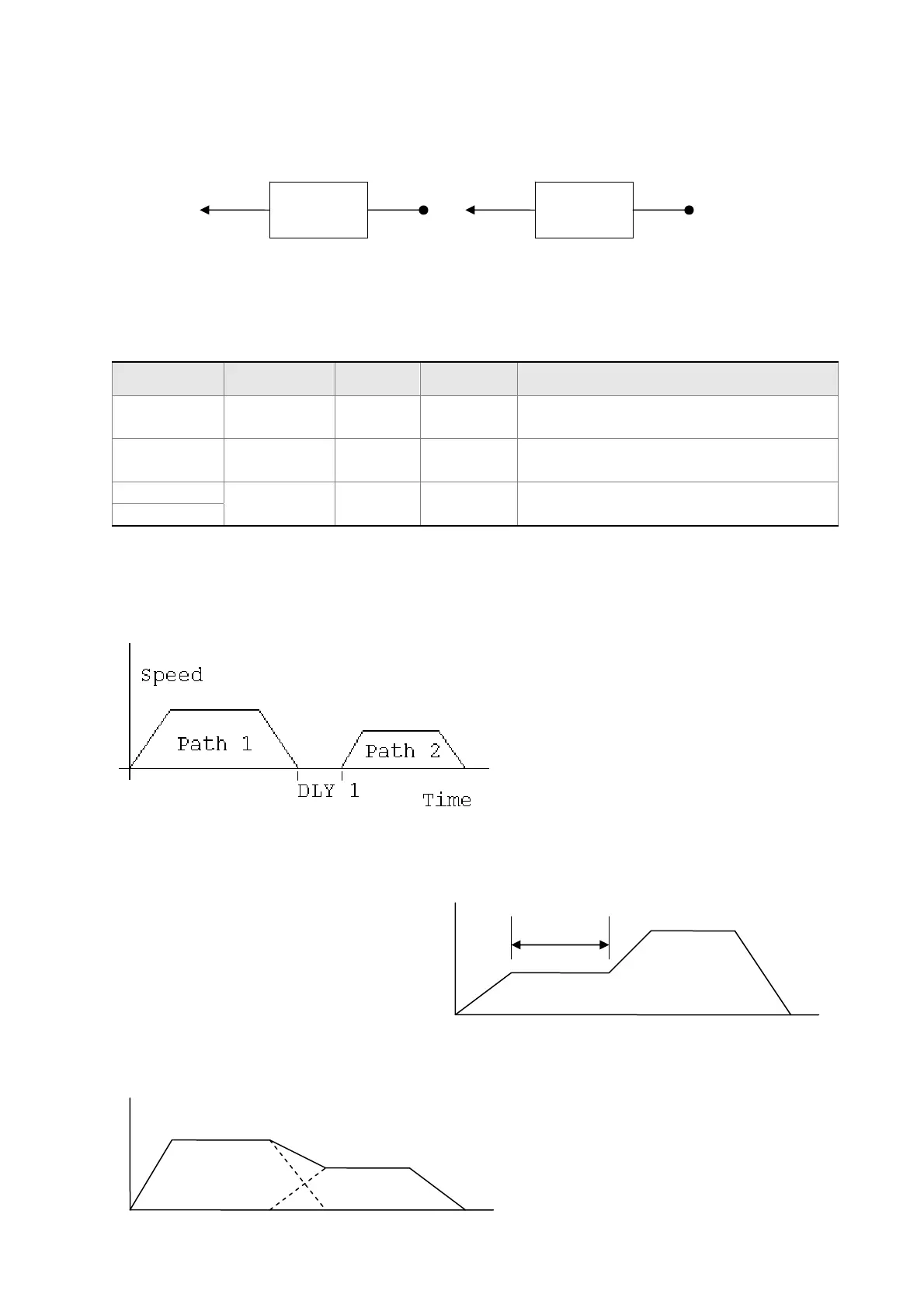
1) Sequence command
Path 1: is AUTO and has set DLY
Path 2: does not set INS
(DLY starts to count after completing
the command)
Path 1: speed command and has
set DLY
Path 2: position command
(DLY starts to count after completing
the command)
2) Overlap
Path 1: has set OVLP but cannot set
DLY
Path 2: does not set INS
Path 1 Path 2
INS OVLP INS OVLP
Path 2
DLY 1
Speed 1
Path 1
Path 2

Table of Contents

Question and Answer IconNeed help?

Do you have a question about the Delta ASD-A2R-0221 Series and is the answer not in the manual?

Delta ASD-A2R-0221 Series Specifications

General IconGeneral
ModelASD-A2R-0221
TypeServo Drive
Rated Output Power2.2 kW
Power Supply Voltage200-230V AC
Max. Input Frequency500 kHz
Control ModePosition, Speed, Torque
Communication InterfaceRS-485, CANopen
Cooling MethodNatural Cooling
SeriesASD-A2R
Power SupplyThree-phase
Control MethodPWM Control
Protection FeaturesOverload, Overvoltage, Undervoltage, Overcurrent
Operating Temperature0°C to 50°C
Storage Temperature-20°C to 65°C
Humidity20% to 90% RH (non-condensing)
Vibration5.9 m/s²

Summary

Preface

Safety Precautions

General safety guidelines, inspection, installation, wiring, operation, and maintenance precautions.

Main Circuit Wiring

Guidelines for wiring the main circuit, including power supply and motor output connections.

Safety Precautions for Linear Motors

Specific safety measures when connecting to linear motors, including electrical hazards and temperature warnings.

Chapter 2 Installation

2.7 Selection of Regenerative Resistor

Guidance on selecting regenerative resistors for built-in and external use based on servo drive specifications.

Chapter 3 Wiring

3.1 Wiring of Delta’s Servo System

Details on wiring Delta’s servo system, including peripheral devices and motor connections.

I/O Signal (CN1) Connection

Details on connecting I/O signals to CN1, including terminal layouts and signal explanations.

Standard Wiring Method

Standard wiring diagrams for common control modes like PT, PR, Speed, and Torque.

Chapter 4 Panel Display and Operation

4.2 Parameter Setting Procedure

Step-by-step guide for setting parameters using the panel interface.

4.4 General Function

Details on general functions like fault record display, JOG mode, and force DO output.

Chapter 5 Trial Operation and Tuning

5.1 Inspection without Load

Procedure for inspecting the servo motor and drive without applying load, focusing on safety.

5.2 Apply Power to the Servo Drive

Instructions for safely applying power to the servo drive and initial checks.

5.6 Tuning Procedure

Procedures for tuning motor parameters, including inertia estimation and auto/semi-auto tuning methods.

Chapter 6 Control Mode of Operation

6.2 Position Mode

Details on position command input methods (PT, PR) and control structures.

6.3 Speed Mode

Details on speed command input methods (analog, register) and control structures.

6.4 Torque (force) Mode

Details on torque command input methods (analog, register) and control structures.

Chapter 7 Motion Control

7.8 Homing Description of PR Mode

Procedure and description of the homing function in PR mode, including Z pulse and coordinate setting.

7.10 Parameter Settings in PR Mode

Detailed description of parameters for target speed, acceleration/deceleration, and path definitions in PR mode.

Chapter 8 Parameters

8.3 Parameter Description

Detailed description of various parameters including Monitor, Filter, Gain, Position, Speed, Torque, and Communication parameters.

Chapter 9 Communication

9.1 RS-485 / RS-232 Communication Hardware Interface

Description of RS-232 and RS-485 communication interfaces, including wiring and configuration.

Chapter 10 Troubleshooting

10.1 Alarm of Servo Drive

List of servo drive alarms, their descriptions, corresponding DO signals, and servo status.

10.2 Alarm of CANopen Communication

List of alarms related to CANopen communication, including error descriptions and corrective actions.

10.3 Alarm of Motion Control

List of alarms related to motion control, including causes and corrective actions.

10.4 Causes and Corrective Actions

Detailed breakdown of common causes and corrective actions for various servo drive alarms.

10.5 Corrective Actions after the Alarm Occurs

General corrective actions for specific alarms like Over current, Over voltage, Under voltage, and Encoder errors.

Chapter 12 Setting of Motor Parameters

12.1 Tuning Procedure of Motor Parameters

Step-by-step guide for tuning motor parameters using PC software or the panel interface.

Related product manuals